Announcement

Collapse
No announcement yet.

Stanley Meyer Explained

Collapse
This topic is closed.
X
X
 
  • Filter
  • Time
  • Show
Clear All
new posts

  • Great Posts!

    From my most recent research:

    It seems the purpose of the Gas Processor is to create a "Electron Cascade".

    On the LED's. I honestly don't believe their purpose is to excite the Oxygen atoms when they are in a high enough voltage field to bring the electrons all the way to ionization. To me it seems that they are used to increase the efficiency of the electron cascade that is taking place.

    Photon Assisted Electron Cascade?

    Chasson321, a few posts back you posted an interesting paper, there I found what I always believed, on page 3. The answer to question (#3c) was:

    Electrical energy raises electrons in the gas atoms to a higher energy level....
    To me it seems once again we can find things that are similiar to Meyers Gas Processor. Like Photomultiplier Tubes (Gas Ionization Tubes) which create a Electron cascade which produces current, the current produced is used on a low voltage circuit and measured for a variety of purposes. (Interesting how very similiar it is to the GP as it has a different form of an Electron Extraction Circuit)

    Photomultiplier - Wikipedia, the free encyclopedia

    Techniques for nuclear and particle ... - Google Books


    On the second link it is explained that photomultipliers can use either a continuous voltage or a pulsed voltage.


    And I'm sure as you all have seen the Gas Processor Circuit, if you understand it, you'll understand that the higher the voltage the engine sensing devices output (RPM, Laser Accelerator) the more electrons will be consumed in the Electron Extraction Circuit, controlling the amount of energy produced in the cylinders of the engine!
    Last edited by HMS-776; 09-02-2009, 11:19 PM.

    Comment


    • @CPU3rotor

      Just an remark on the O3 (ozon) statement
      UV Lamps and Ozone

      I have been in contact whit a company about UVC bulbs and one can choose if one wants ozon or not... from 0ppm to 80ppm/cm3...

      Oneminde
      Last edited by Oneminde; 09-02-2009, 11:06 PM.
      - Behold the truth -

      Comment


      • Originally posted by h20power View Post
        Well, since I really don't see any questions about the water for fuel technology I guess it's time to rest.

        Trying to get me to talk to the three ignors is like trying to get you to poke a needle in your eye, it's just not going to happen.

        If you spend anytime talking to them all you will get into is an arguement. They spend more time posting on this little thread than they do their own.

        So, I will take a break until I have more on the circuit to share.

        Cheers,

        h2opower.
        h2opower, i assure you, there is really nothing importend, what you do miss

        And right, its conspicuous that they do post more in your Thread here as at her own Threads with her Theories.
        Another Mysterie, what is maybe never been solved.
        Theorizer are like High Voltage. A lot hot Air with no Power behind but they are the dead of applied Work and Ideas.

        Comment


        • The mystery is how you think you can replicate meyer projects with 100$
          Being on the wrong track.

          Anyway in my thread you have more info as i said,

          For example from what i read from you, you're trying to put inject the photons 180° de-phased with voltage which is completely wrong.

          Hms-776 You are right to think this way.

          Anyway won't post here anything else if you want to discuss or know more about this make the right questions in my thread.

          http://www.energeticforum.com/renewa...eyer-true.html

          Comment


          • Originally posted by boguslaw View Post
            We all are rotating around the same concept. Basically it is :
            take HV without current (pure potential like) and somehow MERGE with low voltage low amperage electron current displaced from water,ground or air to get incredible power. DO YOU SEE IT ?
            No electronics will help us here, they are planned to be toys.But somebody like Stanley Meyer (and MacGyver also) was patient enough to use toys to build something usable.
            I've seen that one before... It's basically what Aaron said about the Gray tube and the water spark plug.

            I think there may be some truth in that principle, but I am not convinced this is what supposed to happen in the Gray tube, because as Aaron describes it, you basically have two capacitors discharging trough the same path to ground.

            However, it is true that the electric field "governs" any currents occuring in a wire. The field is the cause that gets the electrons moving, and according to Bearden the movement of the electons normally oppose this cause, which he calls "killing the dipole". So, when you're talking about all these electrical systems, the basic problem is how to use/sustain the electric field without "killing the dipole". In this sense, it is important to remember that the electric field is not static, but dynamic. It is a phenomenon spreading at the speed of light and it holds energy. It appears that *all* charges continuously convert zero point energy into electric field energy. I think prof. Turtur calculated how much energy is in the electric field of a given charge.

            Having said that, it certainly is imaginable that you can use electric field A to "boost" a current caused in a wire by field B, if you can direct field A along that same wire, without "killing the dipole" that caused field A. However, as I said, I am not convinced this is what is supposed to happen in the Gray tube.

            Now back to this topic: electrolysis.

            Imagine you have two capacitor plates, which are properly isolated, such that no charge present in any water between the plates can reach the plates.
            Now if you charge the capacitor, you will get a pretty strong electric field between the plates, depending mostly on the applied voltage and the distance between the plates.

            Then two things will (at least) happen. First of all, water molecules are polarised, they are dipoles, because there is an angle between the H and O atoms, so the charges don't completely neutralise one another. That is why water is liquid at relatively low temperatures. Other "lightweight" molecules are gaseous at room temperature, for example.
            So, since water atoms are polarised, they will align themselves along the electric field lines.

            Secondly, water naturally has a certain concentration H+ and OH- ions, which constantly form and re-combine into H2O. This concentration is about 10^-7 for both ion types. What happens if you put water in an electric field, is that these ions will move in opposite directions. The H+ ions will end up at the negative capacitor plate, while the OH- ions will end up dat the positive capacitor plate. This process will continue untill you have such an amount of charge in the water near the capacitor plates, that the field is neutralised.

            And since the ions are pulled apart from one another, the chance of them reccombing becomes less, you will see an increase in the concentration of these ions in your water.

            So far so good. Apparantly, something else also happens. According to Peter Lindemann, something brakes: the "dielectricum inside the capacitor", the water itself. Lindemann said this in a video sometime in 2001. He said that when the tension gets high enough, the dielectricum - the water between the plates - brakes in a "catastrophical" event, releasing a massive amount of gas.
            This is certainly a possibillity. If you make the field stronger and stronger, at some point something brakes inside the water, that's for sure. What brakes exactly and what happens then, I don't know.

            Another possibility is the following. If you apply a (reasonably?) high voltage to the water-filled capacitor, you will end up with a whole bunch of H+ and OH- ions near your capacitor plates. The moment you (rapidly) discharge the capacitor, these ions attrack one-another, so they will move towards the middle of the capacitor. I can imagine that if the tension is high, they will bump into one another and into other water molecules and that this causes enough mess in order for H2 and O2 gas to form.

            So, as far as I can tell there are at least two possible ways how this could be working. In both cases, you need to apply some current to create the field, but the forces the field acts upon the water with, do not cost *you* any current. There may be currents inside the water, but these are induced by the field and are not the result of any current *you* fed into the water, privided everything is properly isolated.

            Comment


            • @lamar

              Thats where the Bedini & Crey voltage spikes commes in. I think that is the reason for your last post.. but this is the wrong tread, this info is more or less not welcome here according to surten members.
              - Behold the truth -

              Comment


              • That "something" lamare is the electron extraction circuit(EEC). The water fuel capacitors work just as you desribed, but you should not put a coating on the postive electrode it should be in direct contact with the water. The negetive electrode should be coated with a dielectric that is imperveous to water like glass or something like that but it must be a dielectric material. When the ions line up close to the positive plate and the EEC is switched on those negetive OH-s are consumed. This happens for the secondary of the VIC transformer is an isolated system no grounds. If you ground the negetive to the earth or chaisy ground when the EEC is switched on all you will get it standerd everyday electronlysis for the EEC is hooked up to a positive source of voltage. Now if the system is isolated from any grounds then when the EEC is switched on the negetive oh- ions have a path to follow thus the lamp or amp consuming device will turn on. This unbalances the equilibrium of the water bath, and the water will strive to correct this umballance by releasing the H+ it does this natrually to restablish equilibrium. The effect that Meyer writes about that after the pulsing has been turned off it still produces gas is due to the imballance caused by the EEC that the water bath still has to correct itself as it feel behind the pulsing speed of the electronics.

                I hope that clears up the "something happens" part of your question.

                More information the WFC's and the WFI's do not work the same way to break down the water molecule. The WFC you now already know. The Water fuel Injectors(WFI) work by charging and recharging the water molecules as they reach the maximum image charge voltage that water can take as a dielectric liquid before it will split into two smaller water droplets dividing the voltage between them as it does. When this occurs the voltage zone of the WFI's recharges the water molecules and the process repeats. This happens over and over again until the water droplet can nolonger split, due to a sort of critical mass has been reached, and releases hydrogen and oxygen gas as a result.

                And Meyer even seems to have figure out yet a third way with the stacked resonante cavities, but I don't fully understand what is taking place with that system, I think HMS-776 has a better grasp of how they work than I do at the moment.

                Now you know two out of three and that aint bad for with that knowlegde you can run an engine provided you use a Gas Processor(GP) in tandam with the three different systems talked about for you will not get much energy content without the GP doing it's job.

                Hope that helps,

                h2opower.
                Last edited by h20power; 09-03-2009, 09:16 PM.

                Comment


                • Thanks everyone for the information:

                  Sebosfato, I believe you've hit the head of the nail with your replies about the email I posted, the photoelectric effect etc. Thank you for the information!!!
                  Last edited by HMS-776; 09-04-2009, 02:14 AM.

                  Comment


                  • why microcontroller is useful and requirements

                    1.
                    To use a microcontroller in Stan Meyer technology can focus different objectives:

                    Subsystems like RPM-, torque-sensoring and control, motor- and water-temperature control can be wired to the microcontroller unit (MCU) and the MCU controls the different ICE regulators. So there is no more need to hard-wire (analog) sensors directly to electronic regulators. The benefit is that changes can be quickly achieved by change in program code instead of rewiring the electronic circuit. That´s the better way for research and prototyping. Microcontroller-code can include lookup-tables for i.e. timing, temperature- and load dependencies. One (or more microcontrollers) become central supervising and controlling instance. System conditions can be easily displayed. The easiest way is via RS-232 interface to the pc/notebook/netbook/pda.

                    The mcu´s features include analog voltage or current sensoring, pwm and of course digital sensoring and control. SM-like opamp-subcircuits from the sensors and to the regulators will be the interface (stub) to the mcu.

                    Sensors and regulators must be defined before wiring and programming the mcu.

                    So the following must be defined first:
                    - ICE sensor electric signal of RPM- and torque-sensors and temperature sensors (device selection)
                    - Time tables for dependencies between i.e. RPM and HV voltage, machine temperature and i.e. water pressure or HV

                    An easy way to program the Atmel mcu is the BASCOM basic compiler (tiny version free), there is no need for assembler coding .

                    2.
                    Trying to get an understanding of the phase lock loop circuit CD 4046 I can see that the voltage controlled oscillation inside the 4046 (VCO) is frequency regulated via pin 9 by a triangular signal created by the TLC555 (rectangular) and the following OPAMP
                    using the 1.58 nF capacitor from the output to the inverting input of the OPAMP (triangular).
                    The resulting triangle waveform enforces a frequency sweep at pin 4 of the 4046 from the lowest to the highest frequency and reverse. Those pins 1,2,13 of 4046 are status signals according to the resonance frequency condition status. Pin 1 and 2 are digital status outputs and get integrated/smoothend by the 2 or-gates and the 10 nF capacitor so that the led “LOCK” can display the locking condition. This signal can be directly or inverted coupled back to the VCO input using one of the two switches in position “Control”.
                    The “DC Voltage” part with those 2 switches I do not fully understand (twice in/out Out/in control). Starting with normal mode condition (triangle wave input to 4046) and exploring the other switches conditions will help.

                    Greetings,
                    bussi04
                    Last edited by bussi04; 09-04-2009, 09:57 AM.

                    Comment


                    • H2OPOWER, Bussi04 seems to know better ways than I do of controlling the engine and parameters. I know very little of microcontrollers.

                      Bussi04, thanks for the info...Looking forward to hearing more from you!


                      Back to the Gas Processor....

                      It seems to me, after finding Meyers statements about electron cascade in his patent, posting the answers I obtained from someone working at NIST.GOV proved the wavelengths used to excite the oxygen atoms are lower than 200nm, which is about as far as LED's go. I don't think the LED's excited the Oxygen atoms. I believe Sebosfato is right when he says the needed wavelength would be in the X ray range. (Perhaps it is why Herman Andersons car had an ionization tube which had to be shielded from the X ray radiation it produced).

                      Sebosfato gave some good references mentioning the Electron Cascade and the Townsend coefficient, which I think is what we're all aiming for in the Gas Processor! It seems to me that we need aluminum electrodes, and 300-303nm LED's to create the photoelectric effect to get the few free electrons we need to start the chain reaction.

                      I would advise everyone to keep an open mind here. I got the book "High Voltage Engineering" by CL Wadhwa on Scribd which explains the Townsend coefficients and how they work to create an electron cascade (avalanche).
                      Last edited by HMS-776; 09-04-2009, 03:56 PM.

                      Comment


                      • Originally posted by HMS-776 View Post
                        H2OPOWER, Bussi04 seems to know better ways than I do of controlling the engine and parameters. I know very little of microcontrollers.

                        Bussi04, thanks for the info...Looking forward to hearing more from you!


                        Back to the Gas Processor....

                        It seems to me, after finding Meyers statements about electron cascade in his patent, posting the answers I obtained from someone working at NIST.GOV proved the wavelengths used to excite the oxygen atoms are lower than 200nm, which is about as far as LED's go. I don't think the LED's excited the Oxygen atoms. I believe Sebosfato is right when he says the needed wavelength would be in the X ray range. (Perhaps it is why Herman Andersons car had an ionization tube which had to be shielded from the X ray radiation it produced).

                        Sebosfato gave some good references mentioning the Electron Cascade and the Townsend coefficient, which I think is what we're all aiming for in the Gas Processor! It seems to me that we need aluminum electrodes, and 300-303nm LED's to create the photoelectric effect to get the few free electrons we need to start the chain reaction.

                        I would advise everyone to keep an open mind here. I got the book "High Voltage Engineering" by CL Wadhwa on Scribd which explains the Townsend coefficients and how they work to create an electron cascade (avalanche).
                        This guy show the example of how every one should research.

                        Einstein showed in 1905 this was possible with his calculations. It depends mostly on the frequency not intensity.

                        Actually as onemind the other in the ignore list posted there are lamps for the production of ozone that have 184nm wavelength or you can go to a another material for the electrode and use a 400nm laser or you can find another material.

                        For an example if you knock an electron from the surface of the potassium using a laser of a wave length of 400nm or +- 3ev you will get an electron witch will jump from the electrode with an energy of 1ev.

                        Until here its ok

                        But if you put a voltage on the anode you will get an acceleration of this electrons F=M*A Or simply

                        If you put 13,5 volts of voltage difference you will have an electron at 13,5 electron volts of energy.

                        To make it more clear think about gravity force is about the same thing the speed of the object becomes greater and greater.

                        _Thats why meyer showed this calculation and stated a voltage potential can't be consumed in an electronic circuit thinking in this way actually it becomes very clear.

                        Comment


                        • Thank you sebosfato!!!

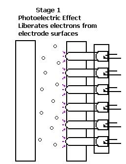
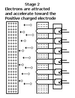
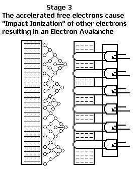
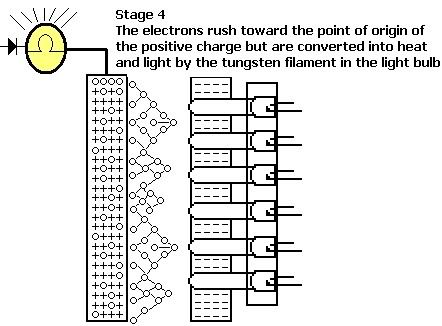
                          Driving today something quickly hit me....All this time Meyer has been talking about exciting the Oxygen atoms to their 4th energy level, and he also mentions ionizing up to 4 electrons from the Atoms.

                          To me the latter makes more sense....I always found it difficult as to how Meyer excited the Oxygen Atoms with LED's (espically after many people told me it could not be done with LED's)....And today I realized...

                          The more electrons that are ionized from the Oxygen atom the greater the imbalance (Attraction force) will be (as there will be more positively charged protons than there are negatively charged electrons). So each electron we ionize from the Oxygen atom, the greater it's positive charge will be and thus the greater it's attraction force to the Hydrogen Atoms electron will be!!!!!

                          Obviously this is the reason for the Electron Cascade Meyer mentions in his Gas Processor patent, which starts from the Photoelectric effect!!!

                          I think This is it!!! The Answer we've been looking for a very long time!


                          To explain the drawings, the Half round objects on the far right are LED's, and the part they are connected to are light guides.

                          We've got this far, but there's still much work to be done!!!

                          References:

                          Electron avalanche - Wikipedia, the free encyclopedia

                          Photoelectric effect - Wikipedia, the free encyclopedia

                          Hertz observed and then showed that electrodes illuminated with ultraviolet light create electric sparks more easily.-Wikipedia-Photoelectric Effect
                          Relativity Calculator - The Photoelectric Effect

                          The problem now is we need to find a widely available material with the lowest photoelectric effect eV, the lower then number the higher the nm will be, meaning the lower the eV the more available the LED's will be. Aluminum has an eV of 4.08 which results in 303nm. Then we can look at calcium which has a eV of 2.9, corresponding to 427nm.
                          Last edited by HMS-776; 09-04-2009, 10:21 PM.

                          Comment


                          • well done
                            Congratulations

                            you see? it's not that hard!!!


                            ps The leds are on the wrong side the electrons come from the cathode negative side.
                            Last edited by sebosfato; 09-04-2009, 10:10 PM.

                            Comment


                            • Good...Every day an new concept.. and nitrogen?? ah...sorry.. the aliens

                              Comment


                              • OK, I was wondering about that when I drew it up, but I wasen't sure.
                                Perhaps that explains why in many of Meyers drawings of the GP he shows the Negative grounded, maybe it's so the free electrons can be replaced from ground to keep the charge neutral, except during the high voltage pulse, in which I believe it becomes negatively charged nearest the positive charge which I have exlplained many times. (Polarization aka electrostatic induction)

                                I have a photomultiplier handbook, it explains alot of things.

                                On page 153 of the Photomultiplier handbook it states:

                                LASERS AND LIGHTEMITTING
                                DIODES
                                In recent years the development of various types of lasers and p-n light-emitting diodes with very high modulation frequencies and short rise times has increased the types of sources that photomultipliers are called upon to detect. Although many of these interesting devices have their principal wavelengths of emission in the infrared beyond the sensitivity range of photomultiplier tubes, some do not. Because of the growing importance of laser applications and the use of photomultipliers for detecting their radiation, Tables F-V through F-IX are providedas reference data on crystalline, gas, and liquid lasers, and on p-n junction light emitting diodes.
                                Just a quick note on Diodes being used, they say many of them are not detected, but that is only because of the material used within the photomultiplier.

                                Comment

                                Working...
                                X