Announcement

Collapse
No announcement yet.

Stanley Meyer technology entering the age of the computer

Collapse
X
 
  • Filter
  • Time
  • Show
Clear All
new posts

  • #16
    Originally posted by theremart View Post
    Hi,

    No offense taken, I understand people who know a certain field much better than I do. I have programmed a little in C++ using the free Borland dos version.
    Nice to see you have tried C++ before.

    So for your interface do you burn your chips on the board or use an socket?
    An AVR PCB has either a 6-pin ISP connector (In Circuit Programming) or a 10-pin JTAG for programming and debugging.

    Some of the family types have "single wire" debugging, just GND, VCC and the Rese/Debug pin.

    Alternatively they can be boot loaded through a communication connection, whatever available.

    I used a pic board because it had power supply and com port built in.

    Would the atmel be able to 1. sense voltage?

    Also what inter up would fire up the micro controller ?
    Yes, all AVR has a 10 or 12 bit ADC (analog to digital converter), they also have 1 or more analog comparators.

    From power down it has to be INT0.
    To get down to 100nA consumption almost every circuit in the uC is turned off.

    Eric

    Comment


    • #17
      There are a few controller-boards worth to consider and I started a thread for that purpose but it didn't take off:
      http://www.energeticforum.com/renewa...placement.html
      If you want an introduction to the Arduino-board the magazine Linux Format did a series of articles (starting in issue 100) and you can read the first one for free:
      http://www.linuxformat.co.uk/include...00.arduino.pdf
      It includes some programming.

      /Hob
      Last edited by nilrehob; 11-04-2009, 08:50 AM.
      Hob Nilre
      http://www.youtube.com/nilrehob

      Comment


      • #18
        @Hob, everyone.

        Finishing the job we have started here involves a lot of choices. But we must not forget the frame and abilities we have at hand.

        It is no secret that only a few here can do uC development at the moment.
        That I'm now trying to change. For the individual following this learning the reward is much increased skills for doing many motor/generator experiments.

        Secondly we have to keep costs down, so this is no barrier.

        The hopefully eventual success will have a lot of design choices, that we right now don't have the conclusive knowledge to take, but luckily bussi04 works on the specification part.

        Meanwhile there is still something we can do.

        Is it realistic to make everyone here a SW developer ? I guess not.
        But I hope a group of 4-10 experimenters will join a first stage of this challenge.

        The reason for the first stage is we need a series of small experiments to make every part of the technology running.

        For this we need eg. the AVR-CAN, which holds the uC, programming and debug connectors and not the least a lot of free pins on connectors we can make good use of on our self built experimentation boards with drivers, FETs, sensor interfaces etc.

        In the second stage we design a board ourself.
        A major requirement (IMHO) for this board is that it must be programmable with just a PC with a single easy to install program, and a binary file do download to the uC via just a USB cable (using the bootloader feature of the uC). As we use cross-platform tools this will work on Linux, Mac and M$.

        This keeps cost at minimum for the many, no special development equipment is needed.

        -----

        But if this has to happen, the first few has to get going, please.

        1. Reserve an old (or new) PC for this task. You can not imagine how much time can be wasted if we do not use the same development environment for the first stage.

        2. Install Ubuntu and the toolchain (instructions pending for toolchain)

        3. Buy a small cheap prototype board, that offers all uC features, probably the AVR-CAN. It has CAN-BUS and many pins free for experimentation. No decision taken yet, I will study the data sheet. Input from others is welcome also.

        4. Buy a programmer or better a JTAG-ICE so the program can be debugged. This is a little more expensive. Maybe we can do with one of the elder inexpensive JTAG-ICE clones, I will check that. The new JTAGs cost dollars.

        ....But don't worry, because this is (hopefully) a joint effort, so we have more low cost options.

        With a complete toolthain HW and SW the development environment works like a charm with turn around cycles below 1 minute.

        We can succeed with just 2 or three guys with full equipment, if...

        We get a taker for a Linux programming task:

        We look to the open source USBprog.

        Here we have all SW ranging from the user interface via USB down to the uC. This is what we need for the second stage for the many. We just have to adapt it to our purpose.

        Then with the USB running, we can adapt the bootloader, and so we can program with just a USB cable, Thats low cost.

        Regarding which processor to choose for the job, I have looked at several processors (but not everything). For the final solution the best I have found so far is the AVR XMEGA.

        They are now into 3'd generation of timers for PWM, and now they have learned the lessons on how to do it right, I have seen other brands with lousy PWM features or too few of then, while the XMEGA has plenty for use.

        So please get going, there is no free meal, I can offer help doing design and development assistance, but there is a severe limit of 24/7.

        --------

        Finally I will state why we need full control from the C++ language, with possible ASM modules if necessary.

        I have made SMPS where I did not use a SMPS controller. I used a tiny45 and programmed the regulation of the output voltage with a fuzzy algorithm of own design. I got 12V with 20mV ripple.

        Basically a VIC is just a SMPS, admittedly a special one

        Eric

        Comment


        • #19
          EBN STOREFRONT - Experimental Boards / Shields

          Comment


          • #20
            Hi carbideTip.

            The concept is right, there is no JTAG controller, but there is the 1 wire "debugWIRE". However the oldest cheap JTAG-ICE clone does not have debugWIRE.

            It only has 2K RAM, and when prototyping I prefer at least 4KByte.
            It is not so good when you in the middle of a project find you have used all memory and need more. I would rather pay 20$ more for more RAM and pins.

            Have a look at the AVR-CAN:

            http://www.olimex.com/dev/images/AVR-CAN-sch.gif

            This will be fine for experimentation, we can build single elements of the final solutions with this one, and when all parts have been programmed and tested, we know exactly what it takes to make the final complete PCB ourselves. And we have all the program peaces come together.

            By buying the AVR-CAN no PCB and solder work for the processor itself is necessary.
            The FET circuits are business as usual. So assemble wise this is a quick starter. Remember to get flat cable and connectors to your own experimentation board.

            @Ronnie,
            Thank you for your decision, hold your horses regarding the JTAG-ICE. I have to finish my fresh install with the tool chain, I have a few things to check yet.

            When ready it will be very easy to do the install as it is almost fully automated, please don't change the original install.

            There are 3 generations of JTAG-ICEs, I have 1 of the oldest JTAG-ICE, and the newer JTAG-ICE mkII. The latest model I don't have, thats the $$ model. You don't need the JTAG-ICE right from the beginning, as there is much you can do and learn without it.

            I will check with my own PCB, if the oldest JTAG-ICE can solve the job, if so, we can go for the cheap clones. Also if it can control the XMEGA we probably will use for the final solution. I hope to have the tool chain and checks ready within the next 24-48 hours.

            Stay tuned

            Eric

            Comment


            • #21
              I manage ubuntu in office, and I find local repository help a lot:
              ftp://kambing.ui.edu/pub/ubuntu-repository/jaunty/

              Unfortunately, only 9.04 version is available right now. the 9.10 might come handy later.

              In case anyone need more help for connecting windows to/from ubuntu, just ask.

              I find qucs help understand the basic circuit simulation. No microcontroller simmulation unfortunately.

              Comment


              • #22
                Originally posted by sucahyo View Post
                I manage ubuntu in office, and I find local repository help a lot:
                ftp://kambing.ui.edu/pub/ubuntu-repository/jaunty/

                Unfortunately, only 9.04 version is available right now. the 9.10 might come handy later.

                In case anyone need more help for connecting windows to/from ubuntu, just ask.

                I find qucs help understand the basic circuit simulation. No microcontroller simmulation unfortunately.
                Hi sucahyo,

                Thank you very much for offering your help

                In return you can learn to use the AVR-CAN as eg. a hex controller replacement, if you add it to your own board with MOSFETS. The AVR-CAN has the uC ready for use with connecters, so your MOSFET part will be easy to do.

                The Atmel AT90CAN128 has 6 PWM outputs from 2 16-bit timers running at 16MHz, it also has 2 8-bit timers.

                With the toolchain you can learn how to make the timing exactly as you wish to, no 555 timer limitations. And you get up to 6 signals precisely positioned to each other, The minimum pulse width is 62.5ns.

                The XMEGA I mentioned has 4 16-bit timers running 128 MHz and a total of 16 PWM outputs, thats a new ballgame for timing applications, it can also read a digital rotary encoder, so the processor knows the rotational angle of a motor/generator with high resolution.

                The minimum pulse width for the XMEGA PWM outputs are approx. 8ns.

                I have an encoder resolving 360 degrees / 40.000, quite accurate

                Regarding the Ubuntu repository.
                I don't know the capability of the Internet in your country, Where I live, I can choose any repository in the world I want to. Maybe you can select a server which have 9.10.

                --------

                Regarding the tool chain I am compiling the CGG compiler right now. When it hopefully succeeds, I have to test everything is OK, to (try) keep you guys out of trouble.

                Eric

                Comment


                • #23
                  Originally posted by hhosteam View Post
                  Tecstatic,
                  What do you think about the Pic micro controller? I know a lot of people like me already have the equipment needed to program the Pic Micros. I don't think it would be that hard to create two different boards, one to use AVR and the other to use Pic.
                  I did expect this question to pop up, on other forums this has almost approached religious dimensions, I have been told.

                  I don't want to see this here, I would say it is a matter of taste, some like the daughter, some like the mother

                  I have tried a PIC some years ago, and much has happened since. Back then I disliked the internal CPU architecture.

                  The normal process is that first comes the CPU, then the compiler was designed.

                  For the AVR it has been built to run code generated from a C compiler efficiently, I like that. To be fair some PICs are now also optimized for C.


                  The PIC has an impressing amount of application notes and designs for practical applications. But still you can peek and do it with an AVR

                  But I't is not my role to decide, I have just made a quick check of the capabilities of the most recent PIC processors.

                  If you think the PIC is the solution to all your dreams, then you can could make a "copy" of my avr_pheripheral library.

                  If we make the SW design completely clean, then it should be possible (but maybe not so easy) to make a pic_pheripherals library, so the choice of library also is the choice of uC.

                  Regarding the compiler it is no simple task to start using a new compiler regarding features and support, the PIC is unknown to me. I know the AVR GCC C++ compiler has been steadily supported for many years now. So for the PIC compiler you are on your own.

                  But that I let up to you. The SW is not the only thing, as we then have to design one more PCB for the final solution. That's extra work, but if there is takers I'm not standing in their way.

                  But IMHO all pulling the same direction is the shortest way to success.
                  I have always had the opinion that you have to do what you are good at.
                  I'm quite fluent in using AVRs, while I'm almost in the dark regarding PIC experience.

                  Believe me having a PIC card and a programmer is just a tiny part of the solution. A complete tool chain and experience to use it + software libraries goes into the equation also.

                  --------------------------------

                  Now I have compiled the tool chain OK, and all seems to work as expected.

                  When do I see the first report of an alternate Ubuntu 9.10 install ?

                  Eric

                  Comment


                  • #24
                    Originally posted by gpssonar
                    Ok here is what i got.....I have a Dell Latitude D600 i am trying to put Ubuntu on... I have the .ISO dowloaded and burned on cd.. I did it exactly the way you wrote in the post. When i boot it it only goes as far showing me logo screens of Ubuntu and stops...Can you help out Eric?
                    This is a very unusual thing, I guess Ubuntu have a minor problem in the new release.

                    I saw this also, the computer locked up, so I took the power, booted again, and it was up running. Has worked fine since, this seems to be related to the very first boot.

                    Please let me know as soon as you have it running.

                    Good work so far

                    Eric

                    Comment


                    • #25
                      Originally posted by Tecstatic View Post
                      In return you can learn to use the AVR-CAN as eg. a hex controller replacement, if you add it to your own board with MOSFETS. The AVR-CAN has the uC ready for use with connecters, so your MOSFET part will be easy to do.
                      Thanks. I don't have resource to do that. I know some assembly, but I never programmed a chip before. I programmed PLC before though, just basic.

                      The ubuntu repository in Indonesia is a complete one version CD iso that can be downloaded. Very usefull for local network installation. Much faster and smaller than doing backup of online repository, and each computer do not have to connect to internet.

                      Originally posted by gpssonar
                      Ok here is what i got.....I have a Dell Latitude D600 i am trying to put Ubuntu on... I have the .ISO dowloaded and burned on cd.. I did it exactly the way you wrote in the post. When i boot it it only goes as far showing me logo screens of Ubuntu and stops...Can you help out Eric?
                      I have experience where newer/older version may stuck at startup screen depend on the computer age. I find using the alternate version is the most reliable. Alternate version use text based installation, link choose the first one if you don't have dual core or higher.
                      http://releases.ubuntu.com/karmic/ub...rnate-i386.iso
                      http://releases.ubuntu.com/karmic/ub...nate-amd64.iso

                      Stuck up at start usually related with display, then the power management. Since dell is popular you will likely get answer at ubuntuforums.org.
                      Last edited by sucahyo; 11-06-2009, 03:27 AM.

                      Comment


                      • #26
                        load problems

                        go into bios and disable power management. most ubuntu systems dont work well with PM drivers and chips... especially on laptops
                        press F6 and enter "no halt" or other ubuntu command line arguments like "no acpi" or "no apic" at the end of the string (google it based on your model of PC or laptop) there are commands that get the linux kernel around these issues... i just dont have them off hand...

                        Comment


                        • #27
                          Microcomputers are good, very good, and much better in performance than analog circuits.

                          But at the same time Stan Meyer used analog circuits for a few reasons.

                          Analog circuits are the simpliest, easiest, and cheapest circuits to build. The electronics newbie can easily build analog circuits at an extremly low cost.

                          Stan Meyer's retrofit system was meant for retrofitting any car, truck, SUV, etc. From all I have seen of it, I think if you had the kit, it could be installed and running within a day.


                          "Idling, low temperature operation adjustments or other calibration adjustments for normal ambient conditions are made by trim pots or in other means included in the management module"

                          -Stan Meyer Patent # 5, 293, 857, paragraph 6
                          The above quote shows us all that by using simple analog circuits, the same circuits could be used for any vehicle, all that is needed is for the user to adjust the pots until things were running right!

                          Another thing, Most all vehicle sensors Meyer used, and most sensors still used today are analog sensors, which are just converted to digital signals. Connecting trim pots to these sensors is really all that is needed to make the proper adjustments, along with the new analog ECU!

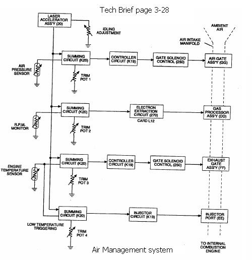
                          And if you look in the Tech brief on page 3-28 you'll see the following which shows the analog block diagram for the circuits which control the engine. This does not include the injector or ignition circuits, which have allready been figured out, and are not really different from a conventional vehicle.


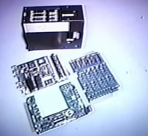
                          The circuit's below show Stan Meyers final work. Notice there are only 3 boards. Quite simple, and not much different than a typical automobile! Looking at the picture below, I do however tend to wonder if the big white block is a microcomputer of some sort. We do know that the injector's were controlled digitally, and perhaps that is where a microcomputer comes into play. Can anyone identify any parts of these circuits?


                          I think a microcomputer would be awesome, but analog is more simple and easy for the less experienced, plus it would be easier to turn a few trim pots that it would be to reprogram the microcomputer 10 times before you got it all right.

                          For those of you who want to know more about how meyers analog circuits worked:

                          http://www.energeticforum.com/renewa...explained.html -See post # 2

                          I'm not knocking microcontrollers. But from what I know they take alot of work. If we want to help others become successful in replicating we need to keep things as simple and inexpensive as we can...
                          Last edited by HMS-776; 11-06-2009, 05:11 AM.

                          Comment


                          • #28
                            Originally posted by gpssonar
                            I got it installed but.......when it tries to load it says Grub loading.
                            error:no such partition grub rescue> I need more help please....
                            Enter bios and check if SATA is not in IDE mode.

                            Comment


                            • #29
                              Originally posted by HMS-776 View Post
                              Microcomputers are good, very good, and much better in performance than analog circuits.

                              But at the same time Stan Meyer used analog circuits for a few reasons.

                              Analog circuits are the simplest, easiest, and cheapest circuits to build. The electronics newbie can easily build analog circuits at an extremly low cost.

                              Stan Meyer's retrofit system was meant for retrofitting any car, truck, SUV, etc. From all I have seen of it, I think if you had the kit, it could be installed and running within a day.


                              The above quote shows us all that by using simple analog circuits, the same circuits could be used for any vehicle, all that is needed is for the user to adjust the pots until things were running right!

                              Another thing, Most all vehicle sensors Meyer used, and most sensors still used today are analog sensors, which are just converted to digital signals. Connecting trim pots to these sensors is really all that is needed to make the proper adjustments, along with the new analog ECU!

                              And if you look in the Tech brief on page 3-28 you'll see the following which shows the analog block diagram for the circuits which control the engine. This does not include the injector or ignition circuits, which have allready been figured out, and are not really different from a conventional vehicle.


                              The circuit's below show Stan Meyers final work. Notice there are only 3 boards. Quite simple, and not much different than a typical automobile! Looking at the picture below, I do however tend to wonder if the big white block is a microcomputer of some sort. We do know that the injector's were controlled digitally, and perhaps that is where a microcomputer comes into play. Can anyone identify any parts of these circuits?


                              I think a microcomputer would be awesome, but analog is more simple and easy for the less experienced, plus it would be easier to turn a few trim pots that it would be to reprogram the microcomputer 10 times before you got it all right.

                              For those of you who want to know more about how meyers analog circuits worked:

                              http://www.energeticforum.com/renewa...explained.html -See post # 2

                              I'm not knocking microcontrollers. But from what I know they take alot of work. If we want to help others become successful in replicating we need to keep things as simple and inexpensive as we can...
                              Hi HMS-776

                              Welcome in this thread, and thank you for your contributions on the subject.

                              I understand what you are saying about the analog circuits.

                              For many (not all) it does not matter regarding complexity whether it is analog or digital.

                              I have worked in both worlds for more than 25 years.

                              What is the circuit complexity for the many ?

                              I guess if we can reduce the work to get one or more PCBs and components, solder it together by following a detailed description with lots of photos, mount it on the car together with the remaining stuff, and do adjustment then we are on the way,

                              This is basically what to do in your perception if I got it right.

                              With a computer you get the possibility of calculating a process, a process which can be easily modified and extended as long as we don't run out of computing power.

                              So when we design an analog circuit, if we get it wrong, we have to design a new PCB.

                              With the digital circuit, in many cases we just need to reprogram.

                              Another advantage is use of parameters, in the analog world a potentiometer, it can be linear or logarithmic, and using it cleverly in the circuit, you can specialize it.

                              With the digital computer, your parameters are just variables in a formula. You can program the parameters in ROM (not flexible), add a potentiometer to an AD converter input to measure the position of the potentiometer (more flexible than the analog circuit, as you can easily change which parameter it adjusts) or you can have a programmed user interface where you can modify parameters as long as you don't run out of computing power.

                              With the analog circuit if we end up, say with 10 potentiometers to adjust, then the 10 parameters are flexible. But maybe we find out that one of the potentiometers isn't really needed, but would be fine for another part of the circuit. Then you have to make a new PCB.

                              With the digital computer you can also add some potentiometers and let the program decide which parameter the pot is adjusting.

                              Add to this drift and non-linear behavior of some process where the formula in a program is superior to a hardwired solution.

                              And reprogramming with the right equipment can be done in less than a minute for a simple change. This is from recognizing eg. a sign, error, correcting the sign, compiling, reprogramming and start running.

                              That is what IMHO is flexibility.

                              I think this is also what Bosch recognized late 1980, first 1990'ties.

                              I have a lot of respect for a Bosch motor controller, I have newer seen any better, some brands as good and I have also seen really lousy controllers a few years ago on some Japanese cars. I think they have solved their issues today.

                              Although I have made more than 30 PCBs within the last 6 years, I can not claim I can do a PCB design cycle this fast. That costs a lot more time.

                              But I admit this view is colored from a what you are used to do, as you may have seen I have stated before, that to a hammer, every challenge looks like a nail.

                              That is also why I speak of two stages, a smaller group doing the programming, and a larger group doing experiments and reporting back for changes.

                              What solution we end up with depends on you guys out there, I'm not doing this alone.

                              The reason i prefer the uC solution is because this way I think we get most bang for our time (and maybe also for the buck), time will (maybe) tell.

                              @suchahyo and TRON, thank you for helping.

                              @gpssonar
                              If the problem persists, it you can seek help on
                              Ubuntu Forums

                              under
                              "Main Support Categories"

                              you have the "Installation & Upgrades" and "Hardware & Laptops"

                              Although I don't sleep much, there is a better chance of getting fast help there for my part, and also I can not claim to have the same expertise as some of the real experts helping there.

                              Good luck.


                              Eric

                              Comment


                              • #30
                                Originally posted by HMS-776 View Post
                                Microcomputers are good, very good, and much better in performance than analog circuits.

                                But at the same time Stan Meyer used analog circuits for a few reasons.

                                Analog circuits are the simpliest, easiest, and cheapest circuits to build. The electronics newbie can easily build analog circuits at an extremly low cost.

                                Stan Meyer's retrofit system was meant for retrofitting any car, truck, SUV, etc. From all I have seen of it, I think if you had the kit, it could be installed and running within a day.
                                ...
                                keep things as simple and inexpensive as we can...
                                Hi HMS-776,
                                in those SM circuits we have explored up yet in the SM explained thread there was not so much overall control and synchronisation purpose realized. it was minimal. those items speed control and gas pressure control from the WFC were very much hard coded in analog and digital logic circuits. the concept originated from WFC technology and there were no circuits for us as templates for control of the injectors.
                                so I think test and experimentation phase (including try and error) can be much faster accomplished by uC than by hard coding and wiring digital and analog devices. the power drivers for VIC, EEC and LED will be the same as in SM digital/analog circuit design.
                                maybe it becomes a lot of work for few of us to do the coding, but for end users it will be downloading and run.
                                once coded the uC programs can be shared worldwide, optimized, plug and play for diffent kinds of applications. additional overall control features will make the end product more reliable (i.e. emergency shutdown by temperature failure in the VIC instead of burning out).

                                The picture might show some kind of uC or some kind of PLA (programmable logic array) or FPGA (free programmable gate array). Those are complex circuits similar to uC and they are programmed in a similar way. while uC are processing more serial those FPGAs process highly parallel substituing discreet digital circuits. maybe Meyer went this way because change in circuits became more complex or timing more critical.

                                greetings,
                                bussi04
                                Last edited by bussi04; 11-06-2009, 09:53 PM.

                                Comment

                                Working...
                                X