Announcement

Collapse
No announcement yet.

Future Energy hydroxy cell

Collapse
X
 
  • Filter
  • Time
  • Show
Clear All
new posts

  • FF Cell

    Yes the first stuff he (wrote or video'd) explained, in there was a certain PWM from ebay but it makes no difference what PWM it is in that the PWM must handle a high continuous current and this should equate to a very high pulsed current.
    Looking into this I found the MX068 model was the same.
    Then he stated he modified it to 15hz. Changed the mosfets to a stronger size (higher current) even though the mosfets on this unit could handle an enormous amount of pulsed current he went slightly higher.

    Lets see if I can find this: (no) if its available it is now harder to find.
    Watching this FF stuff real thorough right from the beggining and everytime I posted a find (on Yahoo group) he pulled video's and he pulled answered email texts at his you-tube and anywhere else. I saved some things like pictures (and he pulled pictures too!) but the video's were not saved. He edited out this information. Have no clue why as he was going to be open source at first.

    Anyways take my word or not its a fact the PWM was modified for 15hz and the mosfets exchanged out as he stated this information at the beginning. (I swear on the BIBLE).

    That field is so close to the 14.3hz Schuman Resonance which are EARTH magnetic field resonant frequencies (check Wiki). Pulsing a magnetic coil at these Schuman resonant frequency's will show you that the magnetic field becomes its full strength at those peaks. Thats a real easy to test and nice to see.

    Now the e-coils on bottom of the tubes were also mentioned in the beginning and trying to find this info, it seems its not available. I'll email you a picture if you want and copy's of my early emails with the information I found before it was edited out. He doesn't show the full coil on bottom because its in the epoxy but the pictures were high enough resolution to blow up 400% and see the wires. Besides that he stated this a s a fact at the beginning.

    The info was pulled because the open source now changed to an upcoming e-book, which for all I know could change too. I'll have to check my sent email folder when I had first sent this information.
    Comment


    • Originally posted by lamare View Post
      The walls are stiff, because of the metal, so you can't get accoustic resonance perpendicular with respect to the tube walls. The resonance has only one way to go and that is in the length of the pipes.
      Hmm. This is not entirely correct. You can have resonance in both directions, but the resonance frequencies in the length direction of the pipes are much lower then the frequencies between the pipes, because of the difference in distance the sound has to travel. This is analog to the difference between closed versus open cylinders:
      Acoustic resonance - Wikipedia, the free encyclopedia
      Note that in this example, the tube is open or half open....

      Both stiff walls and open ends are possible.....

      Comment


      • The info was pulled because the open source now changed to an upcoming e-book, which for all I know could change too. I'll have to check my sent email folder when I had first sent this information
        Oh...Ooo. Well this is new to me... and I expect new to a lot of people here too.

        FF does mention that he doped the epoxy resin at the base with rust, which itself raises a lot of questions, but I've seen or heard nothing of coils at the bottom.

        Anyway, after what you've just stated, I've got a feeling Freddy's out to make some money afterall, and this is all going the way of a big fat scam!

        Comment


        • FF Cell

          Oh forgot to mention no where have I seen here posted about the annealed SS tubing. It undergoes a heat process too! Soften the steel.

          Comment


          • FF Cell

            Try to find this post.
            This is a post answer right from Freddy himself:

            Fred@FEC
            We are not here to scam anyone! Nor are we trying to sell anything to anyone. Please come and see for yourself. Production with the early prototypes netted us only 11.9LPM with over 100 amps! Not until contemplating the best way to cause more chaos in the pressure vessel, analyzing why we were not getting much production, hours of fluid model programs of the flow dynamics of the cell, we have found the following will set you, your HHO project, and your minds free!! The inner tubes are tuned 180 degrees out of phase with the outer tubes. The PWM is tuned to the inner tube resonant frequency. The large center tube set are tuned 4 octaves lower than the outer small pairs. NO coffee this mourning so I am doing the best I can--anyhow-----The square wave pattern produced with the PWM is not the best for accelerating molecules, for it happens so fast, and the molecular density of the water is so low that very few molecules are picked up and propelled. Now if there was some way to build an acceleration ramp and deceleration ramp into the sign wave then in theory we would be able to disrupt the molecular bond of the water more by picking up and accelerating more mass. Well much by accident I discovered that by adding ferrous oxide 10% by weight to the epoxy we use to seal and firmly mount the tubes in the bottom of the vessel, and seal the electromagnetic coils on the bottom of the vessel, it creates a very slow charging and slow discharging capacitor, which smoothes out the sine wave resembling a natural sound wave when viewed on the scope. Also we have achieved further gains in production by working with the upper harmonics of the tube resonance frequency. Also the center tubes have a clearance of 1mm and produce the most heat, the outer tubes are smaller and have a 2mm clearance and run relatively cool, plus having four different tube lengths, diameters, tube thicknesses, adds to the discordant resonance in the vessel. Also take into account that we are producing allot of free radical electrons which act to ionize the HHO and stabilize it when pressurized. The when injected and metered directly into the intake port, decompresses with compression stroke of the motor, a little spark---wala---lots of energy----Please prove me wrong! I personally am doing this for my grandchildren. I would like them to have a world to inherent, that at least has air to breath, and no oil demigod to die for!!!!I have helped as many people as I can perfect tier projects, and this is not my first rodeo with HHO. So please keep your sharp words to yourself until you have ammo to shoot Please!!!


            Tried to upload a 970kb picture, it won't go.
            Attached Files
            Last edited by adam_mizer; 09-21-2010, 09:51 PM. Reason: Double paste!

            Comment


            • Freddy seems to say things that make no sense. Why did he state "sacrificial anode"? I see no erosion of his tubes comparing that vid to previous pictures.

              Why does he state 3 octave difference and not give any reference to a frequency? From what I read you cut frequency in half to move one octave, so if I have a 3/4 inch tube that has a pitch of 1.2k the other tube needs to be at 150 hz (3 octaves lower) or 9.6k (3 octaves higher).

              When he anneals the tubes, what is he going to do? Stick them in a box of carbon and put them in an oven or open fire? Get er done already...

              If Freddy can run his truck %100 on HHO, I think he is lying or got it to work by accident and is trying to act like he knows what is going on but he does not.

              Do any of you know how to make the tubes resonate 180 degrees out of phase?


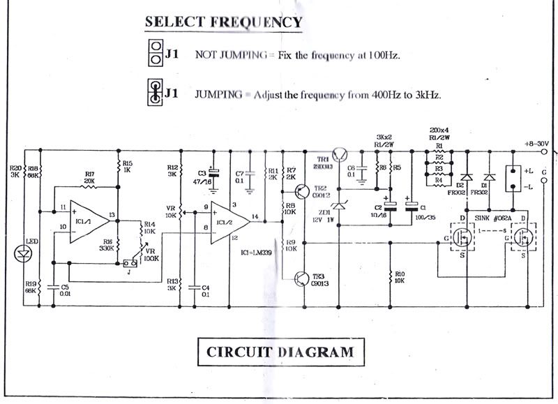
              Here is Freddy un-altered PWM

              Comment


              • FF Cell

                Much of the work of this proto-type 6 is spelled out.
                There are 10 tube pairs annealed 316L SS.
                9 pairs inner are: 3/4" x 7" x 16ga or .065 thickness
                outer are 1" x 6" x .035"
                These tubes are tuned and the gap is 2mm.
                center tube is 4 octives lower than these outer tubes and the center tube has a 1mm gap.
                Tube set is 1.75" x .065 x 7" and 2" x .065" x 6"
                These are virtually tuned at this dimension it may be that they need some minor trimming to tune in closer.
                First cut both 6 and 7 inch tubes, ping or ting them seperately to test their pitch and frequency. It should be the same.
                The large tube set is 4 octives lower, again do them individually.
                Basically this proto 6 tune work is already figured out for you.

                Some annealing approaches can be found on the i-net just search.
                One of the methods was heat to a certain temp in the hundred-teens with a certain amount of time, then cool at a slow rate of certain amount of time after that cool slow cool rate of few hours to equal several hundred degree's less, after they could be cooled quickly. I'm pretty sure Boyce used a annealing method or the plates were preordered annealed. I think we are speaking of a softening process to certain degree.
                Use a small oven like a jewelers oven well maybe the next size or 2 bigger.

                For the 180degree's out of phase may very well have to do with the present gap.

                Comment


                • I suppose we should be grateful for small mercies. At least he hasn't talked about the fabled 'implosion' myth... or water making the pistons go rusty.

                  Rick, I have no idea what he's talking about when he speaks of the inner tube having to be 180 degrees out of phase with the outer. I would have thought, if anything, they would need to be in phase to resonate. Surely 180 deg. out of phase would cause a cancelling action!

                  Somethings sure starting to smell a bit off tho' is it?

                  I sense the 'nobody-believes-me-so-I'm-going-to-have-a-tantrum-and-say-no-more' card is close to being played.

                  Comment


                  • Adam

                    What frequency exactly are the tubes tuned to... and why?

                    Comment


                    • FF Cell

                      Farrah
                      I, like you and many many others am sitting and awaiting the answers to the questions that were asked of Freddy with no reply.

                      I have a hard time wrapping my head around the tuning and found tid bits that pointed to tuning over several years and it somewhat starts making some sense. Meyer Lawton Ravi etc..

                      My garage shop is full of cells built over the years that produce gas but not at the rate of anything I would write about but many are useable as boosters on any motor. There are many feet of left over tubes and plates here and none are small than 1" OD. I am contemplating cutting a 1.75" or 2" OD pipe and checking what the frequency is of that pipe and see if it relates to the 4th octive lower of the small pipes.

                      The information I presented was found when this all started. I had copied what I could at the beginning and now see that posts were removed and pictures changed thats why he has 2 of the same pictures in that 9 picture group.

                      Seeing the posts here the primary Freddy information was starting to get messed up and had missing parts, so I decided to write about what I know.

                      Top this off with Freddy now doing Proto-type 7 which has larger tubes in it than Proto-6 and I wanted answers of Proto-6. Tuning and coils and specific connections to the automotive system (valves used etc..) Seeing that paper on how he started his idea also led me to believe he was using exhaust gas recirculation somewhere but there is no mention of it at all.

                      Over the passed months I have been contemplating building another cell and I found this Freddy info, it intrigued me, took a couple days to sink in and then I started acquiring all the info I could on it.

                      There you have it. Time to take it to the next step or await an e-book.

                      Comment


                      • Originally posted by Farrah Day View Post
                        Rick, I have no idea what he's talking about when he speaks of the inner tube having to be 180 degrees out of phase with the outer. I would have thought, if anything, they would need to be in phase to resonate. Surely 180 deg. out of phase would cause a cancelling action!

                        Somethings sure starting to smell a bit off tho' is it?

                        I sense the 'nobody-believes-me-so-I'm-going-to-have-a-tantrum-and-say-no-more' card is close to being played.
                        No, this is not "off", it's balancing. Yes, you get cancelling out, but not inside the tubes! You basically create a sitiuation that the wave is being contained in a certain area around your tubes, so the energy says there and does not fly away....

                        In other words: you create a loop for your waves to run in circles.

                        Comment


                        • Farrah
                          I, like you and many many others am sitting and awaiting the answers to the questions that were asked of Freddy with no reply.

                          I have a hard time wrapping my head around the tuning and found tid bits that pointed to tuning over several years and it somewhat starts making some sense. Meyer Lawton Ravi etc..
                          Adam, the only real explanation with regards to the frequency of the tube tuning would simply be that they all need to be the same, or in the case of the new centre tubes an appropriate multiple of.

                          However, the question - for me at least - then becomes how are we translating an EM signal into an acoustic signal? Where or what is acting as the transducer?

                          Afterall, it serves little purpose to tune the tubes to an acoustic frequency if an acoustic wave will not be resonating them.

                          Loudspeakers and microphones convert EM signals to acoustic and vice-versa, but there would appear to be no obvious transducer in any of these WFCs. We still have the question as to why FF has deleted his tube tuning videos... and yes, the sceptic in me is starting to take a hold!

                          Comment


                          • Originally posted by Farrah Day View Post
                            However, the question - for me at least - then becomes how are we translating an EM signal into an acoustic signal? Where or what is acting as the transducer?

                            Afterall, it serves little purpose to tune the tubes to an acoustic frequency if an acoustic wave will not be resonating them.

                            Loudspeakers and microphones convert EM signals to acoustic and vice-versa, but there would appear to be no obvious transducer in any of these WFCs. We still have the question as to why FF has deleted his tube tuning videos... and yes, the sceptic in me is starting to take a hold!
                            You either drive a current trough your fluid, which is being carried by the charged ions in the current, or you induce currents inside your fluid using an electric field. In both cases you push/pull the existing ions in the fluid back and forth with a frequency that matches the acoustic resonance frequency of some kind of acoustic resonator in the fluid (your tubes).

                            To me that sounds like a transducer.... It's just not a separate component, but part of the design.

                            Comment


                            • FF Cell

                              Its hard to look at this tuning but there has to be a positive side responce to it.
                              The electric circuit for the cell current cares not for some acoustic resonant cavity, so we have our current in any water or electrolyte to a degree or what we chose for amperage on the design.
                              The tubes are tuned the same but the 2mm gap is now a harmonic of the tubes acoustic base frequency. So the outer tube is now part of the 2mm gap and the inner tube is part of the 2mm gap and also has a fundamental base frequency in its center.
                              But as it fills and expands with gases the 2mm resonant cavity frequency is rising and falling and the stationary center tube maintains its cavity in water no gas.
                              So can the pulsed voltage/current create a vibration between the tubes, reminds me of 60 cycle hum in transformers and flourescent light ballasts. I think there is a slight cavity vibration and also the e-coil attached to the bottom stud helps promote the cycle vibration.

                              Is it possible this creates a desired effect a effect that extends the standard of electrolysis and brings the efficiency up much higher?
                              2 things to look at: vibrational and the effect of a antenna.

                              The frequency of those tubes I'm guessing will be beyond 1000hz I started tuning some 12" tubes a few years ago and never finished and their frequency was from 1-3Khz.
                              The 2mm gaps frequency must be a higher frequency to several Khz, it seems funny that a 15hz pulse can do anything in this so-called acoustic resonant cavity and there is actually a slightly rising and falling frequency change effect on the tubes as the amount of gas verses water space changes.
                              Its interesting to think that maybe a vibrational sound is traveling at 2 different speeds in the cavity of a pair of tubes and we can get a resonant effect out of it. Or is it picking up and inserting radio wave power into the cell.
                              I want to believe it, it has possibility and I havn't seen any real achievements in HHO and this has the building blocks of advancements needed.

                              Comment


                              • FF-cell proto6 pipe tuning

                                I have cut a 2" tube 6 3/32" long x .065" thick my frequency pitch or tone is very near 1760hz which is a "A note". Also cut a 1.75" x 7 3/32" long x .065" thick and the pitch frequency tone is 2217hz which is a C# note and is a major 3rd or 4 semi-tones from an A note:
                                From Wiki,
                                The major third may be derived from the harmonic series as the interval between the fourth and fifth harmonics. The major scale is so named because of the presence of this interval between its tonic and mediant (1st and 3rd) scale degrees. The major chord also takes its name from the presence of this interval built on the chord's root (provided that the interval of a perfect fifth from the root is also present or implied).

                                A major third in just intonation most often corresponds to the fifth partial of the overtone series in relation to the fourth, or a pitch ratio of 5:4 ( play (help·info)); in equal temperament a major third is equal to four semitones — 400 cents, 13.686 cents wider than the 5:4 major third. The older concept of a ditone (two 9:8 major seconds) made a dissonantly wide major third with the ratio 81:64 ( play (help·info)).

                                I had thought something different originally, thinking both pipes would be the same frequency. They are not but they are harmonic to each other. At least this is what my ear hears. I used a demo program:Tone Generator Software - Audio Test Tone Generator Download

                                Playing with this program you can make adjustments to it, my ear is not perfect pitch but can get close. In order for exactness a microphone and pitch or frequency software program must be used.
                                Last edited by adam_mizer; 09-21-2010, 09:49 PM. Reason: Wrong size!

                                Comment

                                Working...
                                X