Announcement

Collapse
No announcement yet.

Basic Free Energy Device

Collapse
This topic is closed.
X
X
 
  • Filter
  • Time
  • Show
Clear All
new posts

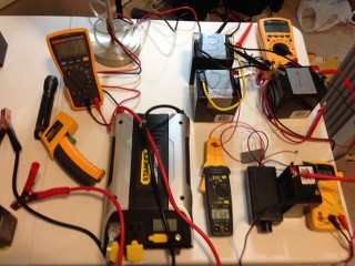
  • After testing the last 2 days I have found with this test atleast that the run time is below simply running 3 batteries in parallel when using manual switching. I am going to order some more parts and try to get the automatic switching working.

    -Altrez

    Comment


    • Originally posted by altrez View Post
      Battery's are a fuel source and with that in mind they wont last forever.
      @Altrez, I have to disagree. With that mindset you fall into the 130+ year trap of science. Batteries are a electrical, potential sink or gate. They can, and have lasted decades, providing dipole differential beyond the chemical engineers wildest expectations. You just have to use that potential in the right way. This is the purpose of the Tesla Switch, 3BGS, Bedini Monopole, and soon Basic Free Energy Device.

      Good Luck,
      Randy
      _

      Comment


      • Originally posted by tachyoncatcher View Post
        @Altrez, I have to disagree. With that mindset you fall into the 130+ year trap of science. Batteries are a electrical, potential sink or gate. They can, and have lasted decades, providing dipole differential beyond the chemical engineers wildest expectations. You just have to use that potential in the right way. This is the purpose of the Tesla Switch, 3BGS, Bedini Monopole, and soon Basic Free Energy Device.

        Good Luck,
        Randy
        Everything I have been studying even the new DvD from John says that they will eat up all the carbon and zinc so with that in mind they are indeed in my mind at least a fuel source.

        -Altrez

        Comment


        • Magnet wire

          Dave
          In post #336 you state to get some 24 gage wire. However the PDF says 23 gage. Just wondering if it matters or which one is better.

          Comment


          • The original Matt Jones pulse motor pdf says to use #23 gauge wire, I believe 50 turns with a single strand, and with that you can build Matt's original pulse motor design. It's an awesome little motor and I have been using it for a year. You can use that motor with a 3 battery setup to see proof of concept, and it WILL WORK.

            HOWEVER

            Matt has been working to put together a motor for you guys that is faster, has more power than the original off the shelf motor (because of no back emf), and returns MOST of the used voltage to the battery so that we can use it (almost for free) to run a generator. This design is based on the things we have learned about how to make it work, and is somewhat different from the motor in the pdf. THIS NEW motor design will use #24 wire and will not be wound the same as in the pdf. May NOT use the same number of turns, and MAY use multiple strands

            TWO DIFFERENT MOTORS but BOTH based on the MY1016 Razor Scooter motor.

            Matt has been testing and testing, and has burnt up a couple motors in the process, as is to be expected. But what he thought would work DOES WORK. He is just trying to make it as efficient as he can, as powerful as he can, before he shares it with everybody. He doesn't want anyone to spend the money to try and fulfill his fantasy. He wants them to be replicating something he has tested and KNOWS beyond a doubt will actually work. SO it may be a few more weeks. Probably after the first of the year. Then you will know haw many strands, how long the pieces should be, and how many turns to put on each segment. We will put together a new pdf.

            I keep telling Matt to take pictures as he winds these things so he has them to share when he is done. But he gets busy and probably forgets. LOL

            The important thing is we know it works, and are just trying to make it better

            Dave

            While I am here, does anyone have a little generator that puts out 24-36 volts rectified to DC?? Has anyone tried substituting the generator for the two 12 volt batteries in the 3 battery setup and running a motor on the potential difference between the generator output and the battery? Now what if the motor you were running was the motor used to turn the generator??? Put an inverter on the battery and run some loads off it.
            “Advances are made by answering questions. Discoveries are made by questioning answers.”
            —Bernhard Haisch, Astrophysicist

            Comment


            • Hello All,

              I have been working on the same three batteries over the last 4 days. I keep thinking they are done but can still get a bit of charge out of each switch. I am giving them longer rest periods now.

              Here is a pic from the current test setup.


              Now the odd thing is that some times for no reason the energy out of nowhere will jump up.

              Here is the series connected batteries voltage at the start on the run.


              10 minites later it jumped up to this:


              It slowly drops back down after that to around 20 volts. I am going to keep testing until I can not charge the load battery any more.

              Might take a while lol.

              I am moving forward with the Tesla switch. I am ordering more parts and meters. The plan is that if I can work on it daily for the next 6 months I should have it working correctly and fully documented with detailed graphs / pictures / videos and deep understanding of how it works and why it works.

              I am going to take all that information and put it into a PDF with a parts list that you can get anywhere and with enough detailed instructions for it to work 100% of the time!


              -Altrez

              Comment


              • Originally posted by Matthew Jones
                Good Luck!! LOL

                Matt
                Go BIG or Go HOME! LOL


                -Altrez

                Comment


                • Altrez,
                  If I were you, (and I will be working on this within a month or so) I would be looking at a five battery system. You already know that when you are rotating the three batteries you can get longer run times, but you want to have a battery that has been charged by an outside source (your generator) to rotate into the mix, as well as a battery that has rested after charging. We know that battery 2 is the battery that loses the most voltage and needs to go to position 3 to be recharged, so when battery one moves to the second position you move your rested battery to position one and your externally charged battery to the rest position. Battery 3comes out to be externally charged.

                  Now this is all only necessary if we can't run the motor (powering the generator) on the potential difference between the generator output (as if it were the two batteries together) and a battery. Can we build a gen run by our modified motor that puts out enough volts and amps to loop our setup.
                  “Advances are made by answering questions. Discoveries are made by questioning answers.”
                  —Bernhard Haisch, Astrophysicist

                  Comment


                  • Originally posted by Turion View Post
                    Altrez,
                    If I were you, (and I will be working on this within a month or so) I would be looking at a five battery system. You already know that when you are rotating the three batteries you can get longer run times, but you want to have a battery that has been charged by an outside source (your generator) to rotate into the mix, as well as a battery that has rested after charging. We know that battery 2 is the battery that loses the most voltage and needs to go to position 3 to be recharged, so when battery one moves to the second position you move your rested battery to position one and your externally charged battery to the rest position. Battery 3 comes out to be externally charged.

                    Now this is all only necessary if we can't run the motor (powering the generator) on the potential difference between the generator output (as if it were the two batteries together) and a battery. Can we build a gen run by our modified motor that puts out enough volts and amps to loop our setup.
                    Hi Dave,

                    Back about 10 pages ago I wrote out one of the setups that I was going to test and it worked pretty much the same way using 3 3 battery setups. Right now I am pulse charging a fourth battery at 60/40 cycles.

                    So far I can't prove that I have had any logger run times even though it seems like I have. After this week I will know for sure if I pass the four hour mark on the batteries I am charging running an inverter with a load of over 50 watts.

                    I know we can build a generator that will do that. And we will build a generator that will do that. Here is my strategic goals for this project.

                    1. Identify an easily reproduced ultra efficient power source for the BFED.
                    a. Tesla Switch

                    2. Build three types of pulse motors.
                    a.Matts razor motor mod
                    b.Qc Motor Generator

                    3. Generator with 12 pickup coils

                    4. Output system

                    Thats what I have come up with so far and its easily a years worth of daily work.. I have a total budget on this project of $7000.00. I have spent almost a grand so far. The big thing for me is documentation with data that has been logged. from the runs. I need to spend another grand just on my data logging equipment alone.

                    My next steps over the next few weeks are to get a simple working build of the Bedini tesla switch in both a 3 and 4 battery setup plus a 6 and 12 volt setup. Have it run for a week with no manual switching and log everything.

                    I feel if I spend the most time perfecting the energy source for the BFED then it will afford me some mistakes on down the road.


                    -Altrez
                    Last edited by altrez; 12-16-2014, 07:20 PM.

                    Comment


                    • Hello,

                      Once I started working on the Tesla Switch I came to the conclusion that I needed a good easy way to check the batteries that I was charging as the load. I purchased a cheap battery tester from Amazon a few weeks ago that I have been really happy with.


                      It allows me to test a battery after a run and see if it really has a good charge or just phantom voltage from the run. It has helped me out greatly.

                      The way I test is I wait for the load battery to reach a certain voltage, after it hits that voltage I let it rest 15 minutes and monitor the voltage. If it remains stable I test it with the Battery test that adds a small load to the battery. If it drops really quick I know it needs more time.


                      -Altrez

                      Comment


                      • Hello All,

                        Last night I added my first transistor to the 3 battery Tesla Switch it seemed to work really well. On the DvD John shares a schematic of a three battery Tesla Switch running a lamp and explains in detail what's going on.

                        The next thing i need to do is get bigger transistors as I melted a few I am going to hook the 6 volt and 12 volt up on two different tables so I can run both at the same time. My logging equipment will log up to 10 volts for the 6 volt switch and I will order a 50 volt version for the 12 volt switch.

                        This is the second level of testing on the concept of the Tesla Switch for me and is a very important part judging from the results last night it looks very promising.

                        For everyone who is following along theses are the steps I would recommend you take to get started on the Tesla Switch.

                        1. Buy the DvD TESLA SWITCH

                        2. Get some batteries that are NEW.

                        3. Start with manually changing the battery position at a set time.

                        4. Add the transistor this will make a lot of sense once you watch the DvD.

                        At that point you will have a very good idea of how this switch works.


                        -Altrez
                        Last edited by altrez; 12-17-2014, 04:45 PM.

                        Comment


                        • hi all.after lots of trial and error i finally got the floppy hub motor running like the computer fan.using power twice and running smooth and fast.
                          this motor has 2.7 ohms dcr for each phase,4 coils,and was harder to tame.here's the circuit.147 uf for c2.r1 and 2 are 1k.diodes are 1n5189.there are 12 coils and 16 alternating poles in the hub.
                          it's a bit crude and could do with some improvements.it's a bit fiddly to start and the circuit wants to flipflop.the current draw is minimal when it's doing this and you just give it a good flick to start it.it starts and runs from 9-10v and up.it's a bit sensitive in that adjusting the timing lights with vr1 changes the rpm.hopefully this sort of timing circuit can be adapted to run any brushless PM motor with a few tweaks.
                          next step is to try loading the generator side of it.i think i will need a switchable capacity setup to make changes to c2 on the fly.
                          pic 4 is a proposed motor gen circuit for 1 driven phase and 2 output phases that are wye connected and center tapped.
                          i got an emax rc motor coming from china.it is said to be .15 ohm dcr and it looks like it has neo magnets.
                          cheers.
                          Attached Files
                          Last edited by voltan; 12-22-2014, 07:02 PM.

                          Comment


                          • Originally posted by voltan View Post
                            hi all.after lots of trial and error i finally got the floppy hub motor running like the computer fan.using power twice and running smooth and fast.
                            this motor has 2.7 ohms dcr for each phase,4 coils,and was harder to tame.here's the circuit.147 uf for c2.r1 is 1000 ohms.r2 is 500.curious, but that's how it goes.
                            pic 2 is a proposed motor gen setup for 2 output phases.
                            i got an emax rc motor coming from china.said to be .15 ohm dcr.looks like it has neo magnets. hopefully i can get that to run too.
                            will add a pic of the hub motor motoring asap.
                            cheers.
                            Nice work! Thanks for the update.

                            -Altrez

                            Comment


                            • Hello All,

                              I have been really learning a lot about how the Tesla Switch should work in a 3 battery configuration. I picked this up from Amazon yesterday to help with the fine tuning of the three battery switch.

                              Siglent Technologies SDG805 Siglent Single Channel 5 mhz Bandwidth Signal Generator, Function Generator, Arbitrary Waveform Generator, 125 MSa/s Sampling Rate: Amazon.com: Industrial & Scientific

                              My next goal is to have a full run with the right transistor in place. I have more parts coming in next week that should be enough to get a simple 3 battery Tesla switch working.

                              The load is becoming a tricky thing to find a sweet spot with. It seems to always need some adjusting on my part the longer it runs in order to get the best charging of battery 3. If I just leave the load constant I always have shorter run times and end up with less real charge on battery 3.

                              However if I adjust the load with a PWM over the course of the run I can really see a difference. Battery 3 always gets a deeper charge and batteries 1 and 2 always drain slower.

                              That brings me to a point that I feel there needs to be some computer controlled load balancing to make this work the best way possible. I would encourage anyone who is experimenting out there to hook up a PWM as the load and then attach a lamp to the PWM and see if you also get better run times when you adjust to the changing charge state of your batteries.


                              -Altrez
                              Last edited by altrez; 12-19-2014, 04:00 PM.

                              Comment


                              • hi altrez.maybe you could use strings of leds and diodes to switch transistors for a bit of regulation.eg 5 bright white leds start to conduct at about 11.6v.
                                where i live, it's cheaper to buy a led torch and pull it apart than to buy leds individually.
                                cheers.

                                Comment

                                Working...
                                X