Announcement

Collapse
No announcement yet.

My Motors got me to Tap into Radiant Energy

Collapse
X
 
  • Filter
  • Time
  • Show
Clear All
new posts

  • Blew my Arduino Uno

    Smoked something near the power jack. specs say 7-12v, up to 18 but not recommended. Plugged in a 12v power supply that was carrying 12.5v, poof. Ordered a new one and a back-up. Can't seem to find a good wall wart in the right range. My AMC has a 9v that drops to 5.5-6v. They say this could give the 5v signal an issue when under 7v. Will have to see... I think its a half-wave rectifier, could go to full there maybe to get some additional voltage. just trying to get some readout on my PC Oscope. Couldn't see any signal, but later I found out that I used the wrong probe (after I fried it). Comedy of errors
    Last edited by sampojo; 08-12-2014, 02:45 AM.
    Up, Up and Away

    Comment


    • Neons to detect back emf in circuit

      Originally posted by Cornboy 555 View Post
      Sorry Joey, I missed this post, the Fets on JS. Monster supposedly can handle 600 V, three 90v neon's in series will let you know when the backrush reaches around 300v, depending on the brightness that they are lit to.

      If they are very bright and blow, Guess what is next, and very quickly, probably before you can push any buttons?

      Regards Friend, Cornboy.
      I could stick a resistor in there maybe to use just one? Amperage to light an NE-1 anyone? may be about .3ma? .6?

      Thanks cornman!
      Last edited by sampojo; 08-12-2014, 03:36 AM.
      Up, Up and Away

      Comment


      • thx1138
        "
        Power

        The Arduino Duemilanove can be powered via the USB connection or with an external power supply. The power source is selected automatically.
        External (non-USB) power can come either from an AC-to-DC adapter (wall-wart) or battery. The adapter can be connected by plugging a 2.1mm center-positive plug into the board's power jack. Leads from a battery can be inserted in the Gnd and Vin pin headers of the POWER connector.
        The board can operate on an external supply of 6 to 20 volts. If supplied with less than 7V, however, the 5V pin may supply less than five volts and the board may be unstable. If using more than 12V, the voltage regulator may overheat and damage the board. The recommended range is 7 to 12 volts.
        The power pins are as follows:
        • VIN. The input voltage to the Arduino board when it's using an external power source (as opposed to 5 volts from the USB connection or other regulated power source). You can supply voltage through this pin, or, if supplying voltage via the power jack, access it through this pin.
        • 5V. The regulated power supply used to power the microcontroller and other components on the board. This can come either from VIN via an on-board regulator, or be supplied by USB or another regulated 5V supply."
        This is out of the Arduino files. If you do further research you will also find that when using 12.0 volts and running a motor or a large string of LED'S, due to the potential higher surges, you will also harm the controller.
        Also keep in mind that the 5v used to power the microcontrolleris NOT the same as the VIN.
        Both the Uno and mega has worked well. Going small with less output pins does limit what it will do, but most will run the monster boards which has four output signals.
        That resistor on the board with no attachment was not intended for the opto.


        Dana
        "Today's scientist have substituted mathematics for experiments and they wander off through equation after equation and eventually build a structure which has no relation to reality."
        Nikola Tesla

        Comment


        • Some AMC improvements

          Upleveled the power supply of the arduino to a full wave bridge rectifier. Hooked up the burnt-up arduino (which I think is overdrawing a bit now) and it only pulls the voltage down to the minimum within spec value of 7v. I previously measured it at 6v pre-burn-up and 5.5v post-burn-up. So yes indeedy the FWBR is boosting power.

          Wow, get this, talk about a dumb****, I was trying to run the monster drivers without the ICs in the sockets

          Making final connections on my Asym Motor Cntlr, will post when completed.

          When that Arduino comes in, I will be ready this time. Due in on Saturday. I will get the diodes blinking or a nice readout on my scope before I do anything else. Meanwhile I think I have a test in mind for my motors with a standard PWM...
          Last edited by sampojo; 08-14-2014, 03:10 AM.
          Up, Up and Away

          Comment


          • AMC Status

            Originally posted by thx1138
            In one of the photos you uploaded with the stuff mounted in the cabinet I noticed near the bottom and to the right that there was a connector marked "A" but it had a black wire. The wires ran outside of the picture so I couldn't see what the other end connected to but that could be confusng if A was for anode and it was the black wire.
            Hey thx, A for Arduino

            my Asym Motor Controller work has slowed for a few days. I have been in the unemployment line for a while but just got some piecework in my field. so drat it got to make some money now.

            But both Arduinos have come in. The newest one is using some very tiny VLSI logic chips. Didn't realize it but I got a Chinese clone, DCcduino. So far OK, uploaded the modified Duoblink code ok.

            Just a few more wires to make on the AMC...
            Last edited by sampojo; 08-20-2014, 03:17 AM.
            Up, Up and Away

            Comment


            • Problem on duoblinkver1

              Assembling my AMC. Here is the Arduino partially connected for testing the Duoblinkver1 program I downloaded. I think Dana made it.

              This picture shows all hooked up to pots to control duty and freq of the pwm out, powered up normally. No blinking LED.

              oked

              The only way I get a blinking diode is by holding my finger on the 2 pins I have sticking out of A0 and A1. Ground does not need any hookup.


              LED blinks rapidly and changes when I press harder or lighter. Finger resistance is about 2M ohm. Pots are 0-10K ohm. Followed directions in the code for hookup. My DCcduino China knockoff does the same thing. And Ground is not even involved. Capacitance of the human body? Don't think I was grounded.


              Dana, Any thoughts?

              thanks a mil.
              Sam.
              Last edited by sampojo; 08-23-2014, 05:50 PM.
              Up, Up and Away

              Comment


              • Problem on duoblink2ver1 continued

                Originally posted by thx1138
                Your green jumper wire from the LED is connected to ground on the Arduino, isn't it?
                Thats the pwm circuit. My finger is on the analog in circuits A0-5. And my finger is completing a circuit between the 2 pins that are supposed to be independent. Can't remember if I tested touching just one.
                I put a link on dropbox.com, not sure if you need to login on your own account to get it or not. Duoblink2ver1@sampojo's dropbox. Let me know if you can get it there. Its for a dual stator motor. Maybe I am getting this behavior because I only hooked up one led... I'll try to check that out tomorrow...

                here is the code
                ---------------------------------------------------
                /* This code was developed for UFOPOLITICS Two brush motors to provide two seperate PWM signals offset in time to reduce AMPS when powering
                on two power lines. As programed here it will provide an OFF setting as well as Frequency control. Higher HZ are avalable
                by adjusting program data but you actually get best purformance at 30 to 32Hz.
                Add 2 LED's and a resistor on each and insert them into (3,10) PWM pin and then both go to ground (for testing). You can use different PWM
                pins as long as you enter there numbers below and keep them in order.
                Turns on and off each LED for 1/2 or less of frequency time, each cycle will do two PWM pins one time with no overlap, repeatedly.
                Install 10K POT WITH CENTER PIN OF POT TO ANALOG PIN (A0). This is the freq. pot and the other 2 pot leads can be switched between
                (+5 to ground) for pot direction. The other (Duty) pot is installed in same manner with center pin going to A1.
                This example code is in the public domain. Developed by PROCHIRO. Tested on Leonardo and Mega2560.
                Code may be simplified and still run all asymetric two brush motors well.
                Important----- Adjust frequency first and then duty for startup (and reverse this for shutdown).
                Pin 13 has an LED connected on most Arduino boards. Do not use 13. If using a LCD for readout, you may find that an
                unexceptable delay and/or distortion will occure. NOT RECOMENDED.
                Give PWM's a name:*/
                int led1 = 3;
                int led2 = 10;
                float ontime= 0;
                float offtime = 0;
                float totalms =0;
                float splitms = 0;

                int freqPin = A0; // Select the input pin for the potentiometer. This can also be be changed as long as you change the pin ID here.
                int dutypin = A1;
                float freq = 0; // Variable to store the value coming from the sensor
                //float freqstore =0;

                int dutyValue = 0;
                char buf[30];
                /*
                This setup routine runs once when you press reset:*/
                void setup() {
                // initialize all 4 digital PWM pins as an output.
                pinMode(led1, OUTPUT);
                pinMode(led2, OUTPUT);

                }

                // This loop routine runs over and over again, forever:
                void loop() {
                dutyValue = (map(analogRead(dutypin), 0, 1023, 1, 50)/2); //
                if(dutyValue<=6){
                return;
                } if(dutyValue>=49){
                dutyValue = 49;
                }
                //freq=30;
                freq = map(analogRead(freqPin), 0, 1023, 1, 200); // full on time for this freq
                if (freq<=2){return;}
                if (freq>=91){freq=91;}
                totalms=(1000/freq);
                splitms=totalms;
                ontime=((splitms/49)*dutyValue)-1;
                offtime=((totalms/2))-ontime;
                //freq=freq-2; //This may be changed to fine tune
                // dutyValue=dutyValue-3; // used to fine tune mid range balance with freq.
                //if(totalms >=200) {
                // return;
                // } // needed for shutdown
                digitalWrite(led1, HIGH); // turn the PWM3 on (1/4 time of total cycle)
                delay(ontime);
                digitalWrite(led1, LOW);
                delay(offtime);
                digitalWrite(led2, HIGH); // turn the PWM10 on (1/4 time of total cycle)
                delay(ontime);
                digitalWrite(led2, LOW);
                delay(offtime);
                dutyValue=(dutyValue*2);
                UpdateConsole();
                }
                void UpdateConsole() { // Same as UpdateLCD() but sending to
                /* Serial.print(" ontime");
                dtostrf( ontime, 7, 1, buf);
                Serial.println(buf);
                Serial.print(" offtime");
                dtostrf( offtime, 7, 1, buf);
                Serial.println(buf);
                Serial.print(" totalms");
                dtostrf( totalms, 7, 1, buf);
                Serial.println(buf);
                Serial.print(" splitms");
                dtostrf( splitms, 7, 1, buf);
                Serial.println(buf);
                Serial.print(" duty");
                dtostrf( dutyValue, 7, 1, buf);
                Serial.println(buf);
                Serial.print(" freq"); */
                dtostrf( freq, 7, 1, buf);
                Serial.println(buf);
                }

                Thx, thanks for your interest and help
                Last edited by sampojo; 08-24-2014, 04:44 AM.
                Up, Up and Away

                Comment


                • Eureka

                  Originally posted by thx1138
                  "Important----- Adjust frequency first and then duty for startup (and reverse this for shutdown)." Did you do this?

                  Double check that your pots are 10K Ohms.

                  I can't tell how the two black wires connected to the Arduino are connected to the potentiometers because the connections are behind the front panel. Should be like this:

                  Code:
                  Arduino +5-----/\/\/\/\-----Arduino Gnd
                                     ^
                                     |
                                     A0
                  
                  Arduino +5-----/\/\/\/\-----Arduino Gnd
                                     ^
                                     |
                                     A1
                  The only other thing I can think of is the code file says, "Tested on Leonardo and Mega2560" and maybe the Uno is different but I wouldn't think so.
                  AHA moment!!!
                  I did not understand that I needed to connect the other end of the Potentiometer to 5v.

                  I have NO 5v line to pots!!!! so that is what "(+5 to ground)" means. 
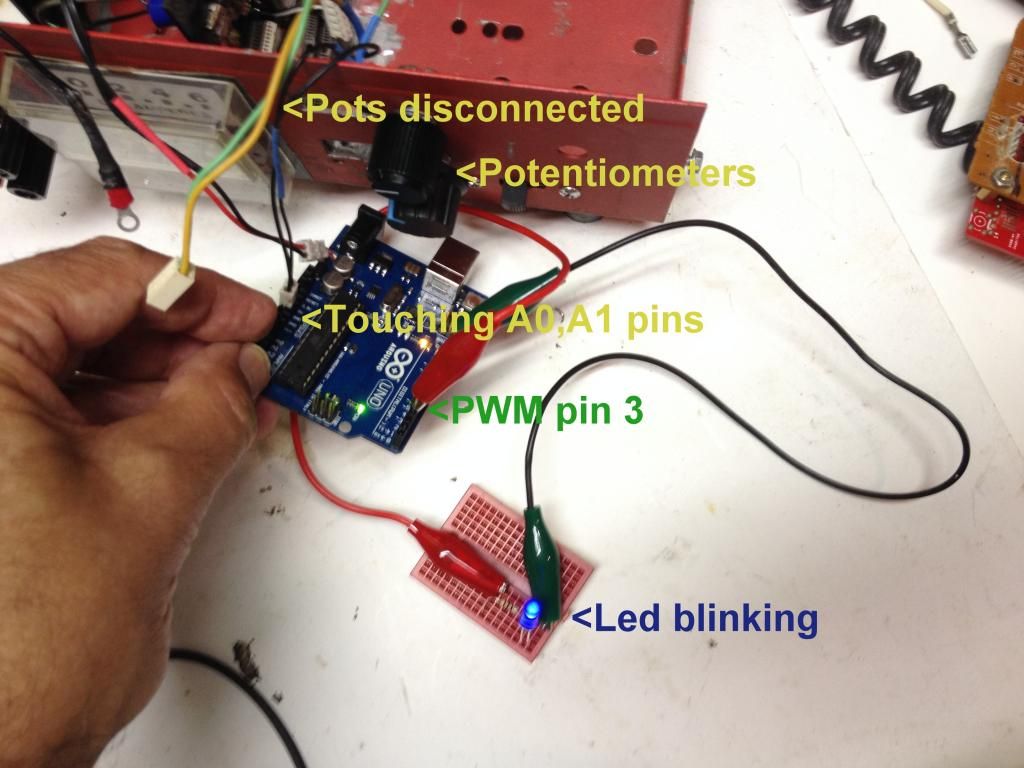
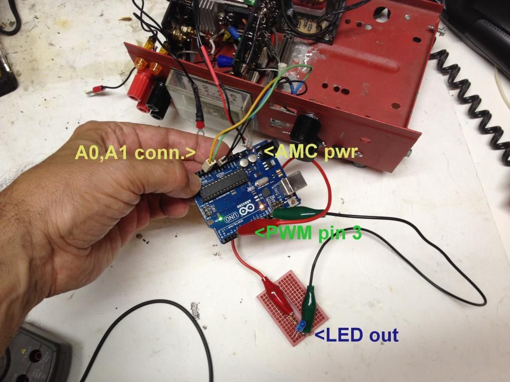
Since I had a 2 pin connector and there are 2 grounds available I ran a ground to each pot, which you can see on the diagram. Green and yellow are A0,1. 5v line AWOL. Luckily I got one single pin connector left in the scrounge pile. Will post results of fix.


                  Great help THX.

                  PS 8-26: Big 10-4 good buddy, DIODES BLINKIN!
                  Last edited by sampojo; 08-26-2014, 01:22 PM.
                  Up, Up and Away

                  Comment


                  • Where's the libraary

                    Nice explanation. thanks again.

                    So where is the code for all the functions like AnalogRead? I thought there might be some include file. I guess the arduino.exe brings it in. Are the functions explained well on their site then? Looks like the Chinese did a nice clone job on the knockoff, just needed a usb driver, talks well with the app.
                    Up, Up and Away

                    Comment


                    • call me fat fingers

                      Burned up all my arduino boards. I must be out $30 bucks bout now. Have some mysterious gremlins. Using a prototype board which is fastened to another board that holds the control unit when installed in my AMC. I started tests without the prototype board, just pins sticking out of the needed Arduino slots with pots and power from the AMC. The first burn-out came when the onboard power supply had my FWBR on it. It got very hot, the LEDs were super bright. The pwm out had 13v on it, full power from the power supply. This was the first time I did not get significant voltage drop when powering the Arduino down to 7v-8v range. Couldn't pull power fast enough for sure. 5v regulation gone, USB dead, no boot up onboard LED flashes, just on steady.

                      Tested the power supply, it was running strange, real hot no load. went back to the original circuit on the power supply, ditched the FWBR.

                      Rolled out the DCcduino china model, started real slow, using 9v battery only, having problems getting control of duty cycle, found a pot went bad, second one. Cheap china pots? Something burn them up? no idea. got some higher power radio shack ones waiting in the wings now.

                      Tried transitioning one item at a time, mounting the arduino on the prototype, then replacing 9v battery with AMC power, reloading software. Got an episode with the 9v battery where the 5v pin was carrying the battery power 8+v, pulled the plug. The thing was scrambled, wouldn't run or get out of the high voltage by cycling power. But a software reload worked and brought it back. Had the LEDs flashing on pins & pots. Started assembling it mounting the prototype board. As I transitioned to AMC power, got it again, 5v pin surged, board dead this time.

                      wonder if a slip of the multimeter probe is a possible explanation... At one point I had the board bottom covered on the board with tape. I was using the analog pins ground off the pots for the PWM tests, trying to get a safe a ground as poss.

                      Ordered some more, try again, assuming I need to be more careful?

                      Classic definition of insanity, keep doing the same thing over and over again, expecting something different to happen?
                      Last edited by sampojo; 08-29-2014, 01:27 AM.
                      Up, Up and Away

                      Comment


                      • Sam,
                        Looks like you are having heaps of fun there. I suggested before and still do that you only power your Arduino with a five volt charger. These surges are coming from unstable power supply and way too much regular power for what you need. If you continue to use this stuff, you will have more bad Arduino's on hand than you know what to do with. No power higher than five volts should be used and I do not care what the data shows or what others say about it. I still have my first one and many others that all work well. I have run the Monster with it on several films and never used more than that. It works. Keep it simple. Anyway, good luck, you are getting there.

                        Dana
                        "Today's scientist have substituted mathematics for experiments and they wander off through equation after equation and eventually build a structure which has no relation to reality."
                        Nikola Tesla

                        Comment


                        • New Arduino Uno, proceding cautiously

                          Pulled the pots out of the AMC, used battery power, pins in the Arduino, got LEDs flashing, mounted the proto board, got flashing again easily. Everything working ok so far. VERY careful with volt meter probe, no accidental touches on anything but targetted pins and readings... Now need to solder on a pin-type conversion connector for walwart type 9v power supply I installed in the AMC. One thing at a time is working so far. Hooked up the fried arduino, (LEDs still come on), pulled a good-looking 10v. Power supply running cool. Wish me luck.

                          Dana:
                          Originally posted by prochiro View Post
                          Sam,
                          Looks like you are having heaps of fun there. I suggested before and still do that you only power your Arduino with a five volt charger. These surges are coming from unstable power supply and way too much regular power for what you need. If you continue to use this stuff, you will have more bad Arduino's on hand than you know what to do with. No power higher than five volts should be used and I do not care what the data shows or what others say about it. I still have my first one and many others that all work well. I have run the Monster with it on several films and never used more than that. It works. Keep it simple. Anyway, good luck, you are getting there.

                          Dana
                          Wow 5v charger. If it is anything like my unregulated 9v it starts out higher and works its way down depending on load. Yeah the Arduino site has a caution about running too low on voltage I shouldnt take to heart then. May have a small 6v laying around...

                          Thanks Dana!
                          Last edited by sampojo; 09-02-2014, 02:46 AM.
                          Up, Up and Away

                          Comment


                          • Sampojo
                            Actually I used a seven volt walwort which by the time it gets in the Arduino, is just fine.
                            Dana
                            "Today's scientist have substituted mathematics for experiments and they wander off through equation after equation and eventually build a structure which has no relation to reality."
                            Nikola Tesla

                            Comment


                            • power, arduinos, ruggedinos

                              Trashed another Arduino. Working too late into the AM. Reversed polarity on Vin. All that blew is the PWM out pins, won't drive anything. Or accidental grounding there, tried to be more careful with the probe. 5v still good, still loads a program and talks to the PC. Ordered Some Atmega chips for a few dollars. Just too excited about building my AMC. That ruggedino sounds better and better. They sure got me nailed, making mistakes. They made that bullet proof. For power reversal, lapped in a blocking diode. Won't get me again! That's what they put in the ruggedino too.


                              Well I used my FWBR on my 6.2vAC transformer, now it puts out 9v But at least it doesn't start out at 13v like the other, but stays at a higher voltage. Seems more stable. Maybe I can use one of those cell phone chargers?

                              Well I guess its time to put the finishing touches on the AMC as I wait for parts, maybe rebuild my Quad Pentium window motor with a new unipolar rotor. Also working on a small AC generator, gotta put "exciters" in it, (magnets). Bit the bullet and just ordered the exact arc magnet, had to get neodymiums though. Hope they aren't too strong... Looking to make a minature imperial-Mecce Alte setup, hook up the AMC and who knows, replace the battery with super caps, if you catch my drift...

                              EUREKA, found my problem, my prototype mounting board has what I thought was a power strip just labelled for the fun of it at 5v and I used it to mount power in. Guess what, I have been sending input power back down the throat of the 5v Arduino line. Didn't see any cricuit until I looked for it, held it up to the light. I need that location on the prototype board so I will break that circuit. What a waste, what an idiot
                              Last edited by sampojo; 09-05-2014, 04:36 AM.
                              Up, Up and Away

                              Comment


                              • AMC Assembly complete

                                For a dual stator motor. Expansion plans for a quad stator, as soon as I build the next 2 driver boards. Ammeter just gets MD2 circuit amps.

                                > Arduino operation A-OK, has its own 9v pwoer.
                                > Monster drivers only verified for 5v and 12v voltage regulator operation, power 18v

                                Here is what it looks like:


                                Internal wiring view:


                                Now to get the monster drivers working.

                                I have loaded the Duoblink program for the dual stator, and ran a check with the blinking diodes.

                                Need to verify that the monsters are getting power.

                                Is it correct that the first indication of correct operation would be the diodes on the Monster driver boards should be on and I should be able to control their blinking rate (and intensity also with the duty cycle), without the motors hooked up at all?
                                Last edited by sampojo; 09-13-2014, 08:28 PM.
                                Up, Up and Away

                                Comment

                                Working...
                                X