This forum is preserved as a permanent archive. The community continues at eMedia Press.

Announcement

Collapse
No announcement yet.

Perpetual Motion Simplified - Asymmetrical Mechanical Machines

Collapse
X
 
  • Filter
  • Time
  • Show
Clear All
new posts

  • Perpetual Motion Simplified - Asymmetrical Mechanical Machines

    Hi folks, after studying Mikhail's discovery and all the prototypes that have followed by Mikhail, Charlie, Ron, Greg, myself and numerous others for nearly 3 years.


    Here is my current design path:
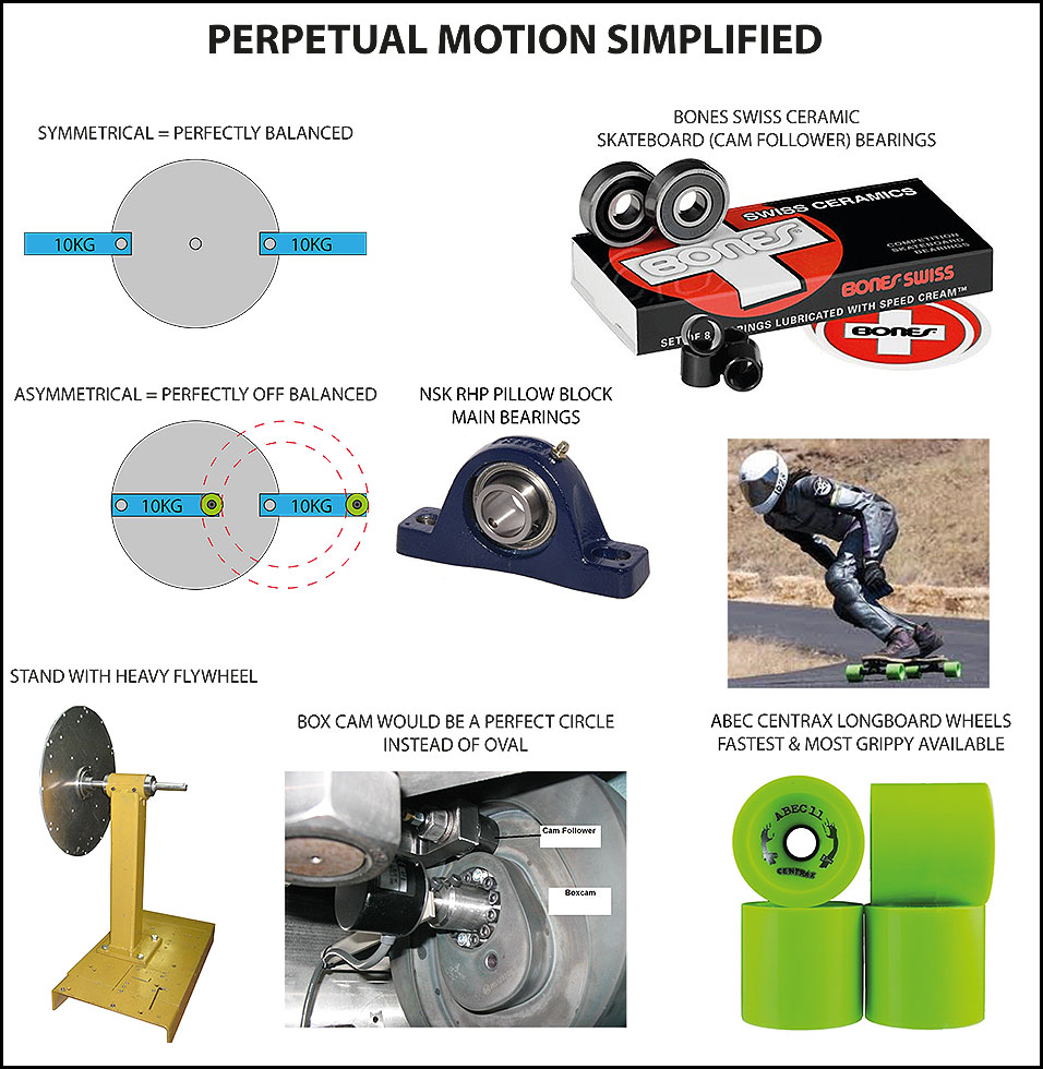


    The only thing missing from the picture are the Sprag clutch bearings with "zero backlash".
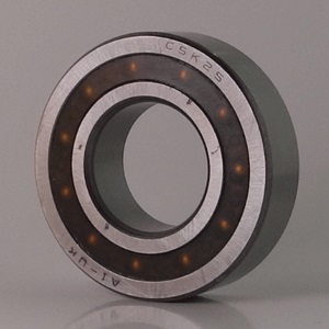


    Stieber CSK20 20mm Sprag Clutch One Way Bearing Without Keyways 20x47x14mm

    Stieber CSK20 20mm Sprag Clutch One Way Bearing Without Keyways 20x47x14mm 10-14 Simply Bearings Ltd

    "This range of clutches can be used as freewheels and can be used in backstop, overrunning or indexing applications. Freewheel bearings are characterised by their ability to turn in one direction only and thus transmit torque whilst having a zero backlash They are supplied filled with grease and are low maintenance. The torque is transmitted on the inner and outer race by an interference fit into a rigid housing and onto a shaft. The tolerance for the housing fit is N6 and the tolerance for the shaft is n6. Operating temperature range: minus 40 deg F to plus 212 deg F or minus 40 deg C to plus 100 deg C"


    I'm building it in the new year if everything goes to plan.

    I will post the Solidworks design once it has been advanced a little further.

    I've researched the components quite thoroughly and I'm pleased to say they are mostly off the shelf.


    In every position the wheel is at maximum off balance.

    The frequency could also be doubled by having another wheel and box cam the other side.

    As the diameter increases, so can the arm length.

    Of course, this could be coupled with UFO's asymmetrical discoveries for an even more interesting outcome.

    No radioactivity, cannot be suppressed, easy to understand by the layman.


    I think this is the one folks. I don't think it can get any simpler.


    Thoughts welcomed please.


    Best regards,

    Paul
    Last edited by soundiceuk; 12-04-2013, 06:08 PM.

  • #2
    Originally posted by soundiceuk View Post
    Hi folks, after studying Mikhail's discovery and all the prototypes that have followed by Mikhail, Charlie, Ron, Greg, myself and numerous others for nearly 3 years.


    Here is my current design path:


    The only thing missing from the picture are the Sprag clutch bearings with "zero backlash".


    Stieber CSK20 20mm Sprag Clutch One Way Bearing Without Keyways 20x47x14mm

    Stieber CSK20 20mm Sprag Clutch One Way Bearing Without Keyways 20x47x14mm 10-14 Simply Bearings Ltd

    "This range of clutches can be used as freewheels and can be used in backstop, overrunning or indexing applications. Freewheel bearings are characterised by their ability to turn in one direction only and thus transmit torque whilst having a zero backlash They are supplied filled with grease and are low maintenance. The torque is transmitted on the inner and outer race by an interference fit into a rigid housing and onto a shaft. The tolerance for the housing fit is N6 and the tolerance for the shaft is n6. Operating temperature range: minus 40 deg F to plus 212 deg F or minus 40 deg C to plus 100 deg C"


    I'm building it in the new year if everything goes to plan.

    I will post the Solidworks design once it has been advanced a little further.

    I've researched the components quite thoroughly and I'm pleased to say they are mostly off the shelf.


    In every position the wheel is at maximum off balance.

    The frequency could also be doubled by having another wheel and box cam the other side.

    As the diameter increases, so can the arm length.

    Of course, this could be coupled with UFO's asymmetrical discoveries for an even more interesting outcome.

    No radioactivity, cannot be suppressed, easy to understand by the layman.


    I think this is the one folks. I don't think it can get any simpler.


    Thoughts welcomed please.


    Best regards,

    Paul
    Hi Paul

    Looking good; what sort of wattage will you be using for the prime mover and what are you hoping/estimating the output to be?

    Regards

    John

    Comment


    • #3
      Hi John, I envision two different systems.

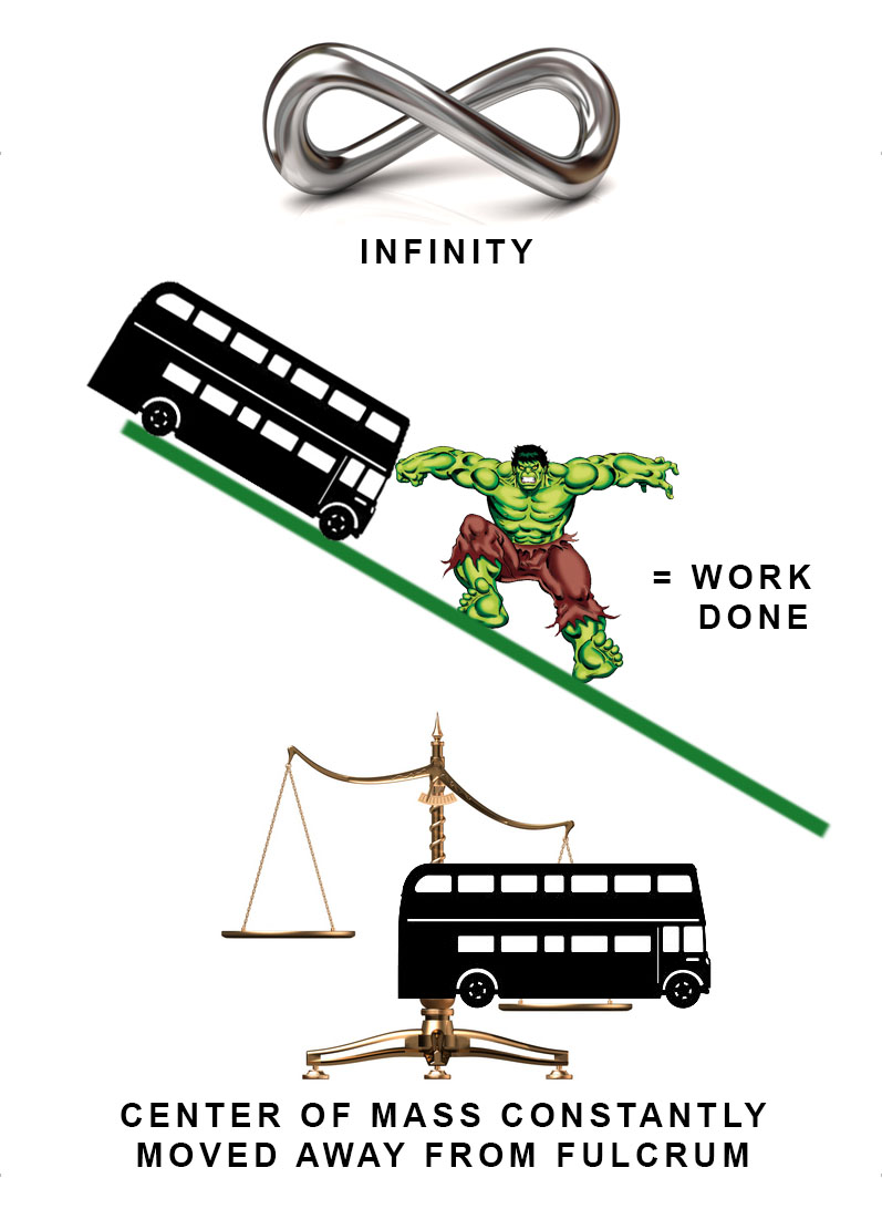
      Both systems work because of the "center of mass".

      Center of Mass - Dr. Carlson
      Center of Mass - Science Theater 29 - YouTube

      Center of Mass - David Taylor
      Center of Mass - YouTube

      Center of Mass - James Dann
      Center of Mass - YouTube


      The 1st system would need to be stopped from cascading using one or a number of 12v car alternators, a battery/s or an ultra capacitor and a load.

      The reason for using a car alternator is because the RPM will vary under different loads and the alternator outputs DC. The system could run at night, charge the batteries or capacitor for use in the day.

      It could also run continuously or be monitored and controlled by electronics.

      The load prevents the RPM from cascading too high. The weight of the flywheel and arms would need to be matched to the required output, otherwise the RPM would runaway.

      The NSK RHP main bearings are the highest quality best off the shelf pillow block bearing available and have a maximum RPM of 7400RPM.

      I think we can easily accommodate a system that runs within that speed.


      The 2nd system would be driven by a prime mover at a particular RPM such as 1500RPM or 3000RPM and matched to an off the shelf or custom mains voltage generator.


      I am building the device to prove perpetual motion is a reality and either let it cascade to destruction on video, or have it connected to a engine dyno that will measure BHP and torque.

      My job will be done when it is presented to the world's heavily indoctrinated mechanical engineers that keep telling me it is impossible via youtube.

      The centre of mass is never in the middle of the main shaft with this design.


      Here are a few simple experiments anyone could try.

      1. Balance a length of wood or metal on your finger.

      Now move your finger very very slightly to the left or right to change the centre of mass.


      2. Take two 5 kg (or heavier or lighter) dumbells. Stand with your body symmetrical and the dumbells extended horizontally.

      Now stand in the asymmetric position with your arms facing horizontally the same way and feel the difference.

      If your brave stand on one leg and repeat the experiment.


      Now remember, the device is a wheel with a centrally located spindle.

      Another fact to consider is that inertia, centrifugal force, centripedal force will assist because the skateboard wheel (cam follower) has no where else to go apart from in a lovely perfect circular motion.

      Can you follow my chain of thought now?

      Best regards,

      Paul
      Last edited by soundiceuk; 12-05-2013, 11:36 PM.

      Comment


      • #4
        Hi folks, this is what I see.


        Mechanical amplifier - Wikipedia, the free encyclopedia

        Non-resonating amplifiers

        Main article: Mechanical advantage

        Levers and gear trains are classical tools used to achieve mechanical advantage MA, which is a measure of mechanical amplification.

        Lever

        A lever can amplify either displacement or force.
        Lever can be used to change the magnitude of a given mechanical signal, such as force or displacement.[1] Levers are widely used as mechanical amplifiers in actuators and generators.[11]

        It is a mechanism that usually consist of a rigid beam/rod fixed about a pivot. Levers are balanced when there is a balance of moment or torque about the pivot. Three major classifications exist, depending on the position of the pivot, input and output forces. The fundamental principle of lever mechanism is governed by the following ratio, dating back to Archimedes.
        \frac{F_A}{F_B} = \frac{a}{b}
        where FA is a force acting on point A on the rigid lever beam, FB is a force acting on point B on the rigid lever beam and a and b are the respective distances from points A and B to the pivot point.

        If FB is the output force and FA is the input force, then mechanical advantage MA is given by the ratio of output force to input force.
        MA = \frac{F_B}{F_A}


        There must be a totally different set of maths for a lever in motion.

        Maybe a welcoming science / maths professor would know perhaps? Then again, maybe this is a lost mathematical art.


        Best regards,

        Paul

        Comment


        • #5
          UFO posted this Archimedes quote the other day which I had never heard before.

          Makes sense though.


          Here is my quote:

          "Give the people an asymmetric perpetual motion machine and they shall power the world!"
          Last edited by soundiceuk; 12-06-2013, 02:47 PM.

          Comment


          • #6
            Hi folks, my latest notion:


            Best regards,

            Paul
            Last edited by soundiceuk; 12-07-2013, 10:14 PM.

            Comment


            • #7
              equal weight the same 1 foot) just to keep everything running.

              Now if we are to get a useable output power then the falling 10kg over is 1 foot distance must be able to lift a weight greater then 10kg up the same 1 foot distance. If you can do that then you got something.

              Comment


              • #8
                I have built many over balanced wheels over the years. Out of all of them, only three showed any promise of being capable of self running. The main reason they didn't is because of a lack of precision build. Mostly these were prototypes designed on a CAD then built quickly without reqard to detail. if I had taken the time to do a complete build adhering to specific tolerances, then they may have worked. Mostly though, I was only proving the principle of over balancing wheels in general. I have two designs that I haven't built a prototype of yet that may prove to be self runners. I only know of two people in history that have achieved a self running over balance wheel, and neither one has been successfully replicated even though the parts for one of them was salvaged and replaced. Hopefully we can either replicate or design one that works because gravity works everyday, all day, 24/7, without any other outside force except gravity. Good Luck. stealth

                Comment


                • #9
                  Originally posted by Mad Scientist View Post
                  Unbalanced wheels have always been a fascination for me.
                  Hi Mad Scientist, they have for me too for nearly 3 years.

                  Originally posted by Mad Scientist View Post
                  equal weight the same 1 foot) just to keep everything running.

                  Now if we are to get a useable output power then the falling 10kg over is 1 foot distance must be able to lift a weight greater then 10kg up the same 1 foot distance. If you can do that then you got something.
                  I designed this using Solidworks with some help from a number of folks earlier in the year:


                  I never got around to increasing the number of weights to 4, but here is a slightly ropey video I quickly made to show some of the forces at play.


                  The weights are just a little over 10kg.

                  The main bearings are cheap ones and are misaligned.

                  When the arms are raised to the 3 o'clock and 9 o'clock position, the torque on the main shaft feels quite substantial. Substantial enough not to risk holding it for fear of mangling hands and arms.

                  It only recently dawned on me that the reason the prototype comes to a stop is not just because of the high friction of the cheap misaligned main bearings. It is because the centre of mass is no longer in a position to overcome the friction.

                  Mass is very important for a perpetual motion machine to produce usable torque.

                  If an ant got onto a see saw it wouldn't budge.

                  If a cat got onto a see saw it might move a little.

                  If an elephant got onto a see saw, it would be quite extreme, but not as extreme as a navy ship though!


                  So after watching the prototype video would you agree that it appears we have something special here?

                  Best regards,

                  Paul
                  Last edited by soundiceuk; 12-07-2013, 11:06 PM.

                  Comment


                  • #10
                    Originally posted by Stealth View Post
                    I have built many over balanced wheels over the years. Out of all of them, only three showed any promise of being capable of self running. The main reason they didn't is because of a lack of precision build. Mostly these were prototypes designed on a CAD then built quickly without reqard to detail. if I had taken the time to do a complete build adhering to specific tolerances, then they may have worked. Mostly though, I was only proving the principle of over balancing wheels in general. I have two designs that I haven't built a prototype of yet that may prove to be self runners. I only know of two people in history that have achieved a self running over balance wheel, and neither one has been successfully replicated even though the parts for one of them was salvaged and replaced. Hopefully we can either replicate or design one that works because gravity works everyday, all day, 24/7, without any other outside force except gravity. Good Luck. stealth
                    Last edited by soundiceuk; 12-07-2013, 11:08 PM.

                    Comment


                    • #11
                      Well unfortunately no. What I see is a nicely balanced wheel. As long you keep pushing it, it keeps turning. When you stop the momentum keeps it turning for awhile, but it eventually slows down and stops. Adding more weights will only make it heaver but not affect its balance. I would expect a true gravity wheel to be self startingin balance but there still would be no movement.

                      Been there, done that.

                      So as one weight is moving down the other weight has
                      The trick here is the two weights are always held in a horizontal position by a chain connected to a non-moving sprocket and the center. So as can be seen in the drawing as it turns one weight will always be farther from the center the other. It is obvious this has to work plus his 6 pages of calculations however he never did actually build a working model cause if he had he would have found the system was always in perfect balance.
                      The reality here is the two weights move around in a perfect circle about an imaginary center that is offset from the real center.

                      Comment


                      • #12
                        Originally posted by Mad Scientist View Post
                        Well unfortunately no. What I see is a nicely balanced wheel. As long you keep pushing it, it keeps turning. When you stop the momentum keeps it turning for awhile, but it eventually slows down and stops. Adding more weights will only make it heaver but not affect its balance. I would expect a true gravity wheel to be self starting.
                        Hi, I'm not sure we are on the same page yet buddy.

                        Before I can respond to the rest of your post, I just need to clarify that you watched the video?

                        The reason I say this is because you wrote:

                        Originally posted by Mad Scientist View Post
                        OK so happens if you were to replace the bearings with one-way-bearings.
                        Cheers,

                        Paul

                        Comment


                        • #13
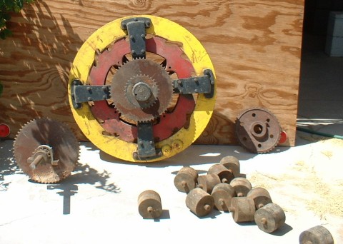
                          Yes, one is Besslers and the other is buzzsaw wheel. Both were seen in operation by many people who swore to their self running characteristics. The Buzzsaw wheel was found, cleaned, put back together but still they couldn't get it to work. Those who saw it work claimed it ran a sawmill, which required quite a bit of power. It seems there was some missing parts and no one knows remembered what those parts were. I haven't built either one of these but I have built several others. One of the candidates for self running I've built is the rolling ball motor. Another is a D design chain rolling on three cogs, where the long round part is much longer than the short verticle reloading side. Here is a picture of the rolling ball. Good Luck. stealth
                          Attached Files
                          Last edited by Stealth; 12-08-2013, 01:05 AM.

                          Comment


                          • #14
                            Originally posted by Mad Scientist View Post
                            The reality here is the two weights move around in a perfect circle about an imaginary center that is offset from the real center.
                            Have a look at the 1st picture I posted in the thread with the "Asymmetrical = Perfectly Off Balanced" above it.

                            See the dashed red line.

                            This is the path the skateboard wheels will follow on the boxcam.


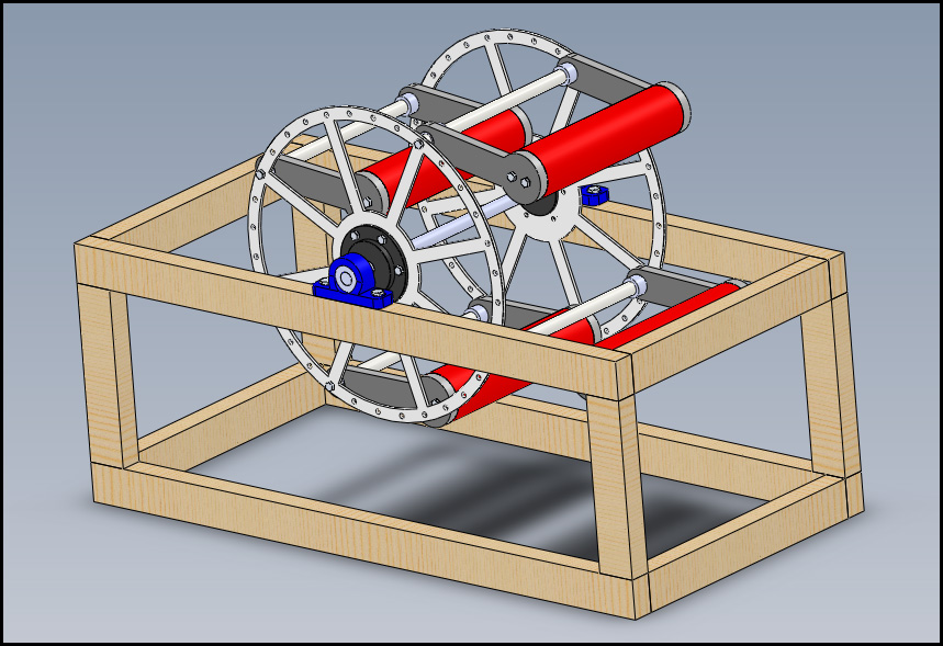
                            Here is the first Solidworks draft to explain visually where I am going with it.

                            There would be another piece joining the center of the boxcam with the outer part.

                            I plan to water jet the whole lot from 28mm steel plate.


                            All of it would mount to a frame made from 50mm x 3mm box section steel tube.


                            Of course, the blue weights (arms) can be extended considerably as long as they don't contact each other.

                            I will post more when I have time to advance it.

                            Best regards,

                            Paul
                            Last edited by soundiceuk; 12-08-2013, 01:25 AM.

                            Comment


                            • #15
                              Originally posted by soundiceuk View Post
                              Hi, I'm not sure we are on the same page yet buddy.

                              Before I can respond to the rest of your post, I just need to clarify that you watched the video?
                              Paul
                              Yes that is for sure and Yes I did watched the video but all I see is a freely turning wheel with weighs that will fly out when turned. To thatpluspaddle wheel that was driving the mechanism not the other way around

                              Comment

                              Working...
                              X