This forum is preserved as a permanent archive. The community continues at eMedia Press.

Announcement

Collapse
No announcement yet.

X-ray unit tank circuit pictorial part1

Collapse
X
 
  • Filter
  • Time
  • Show
Clear All
new posts

  • X-ray unit tank circuit pictorial part1

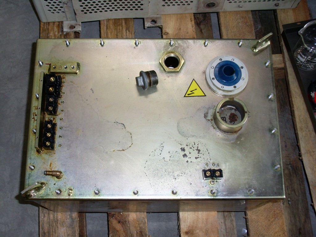
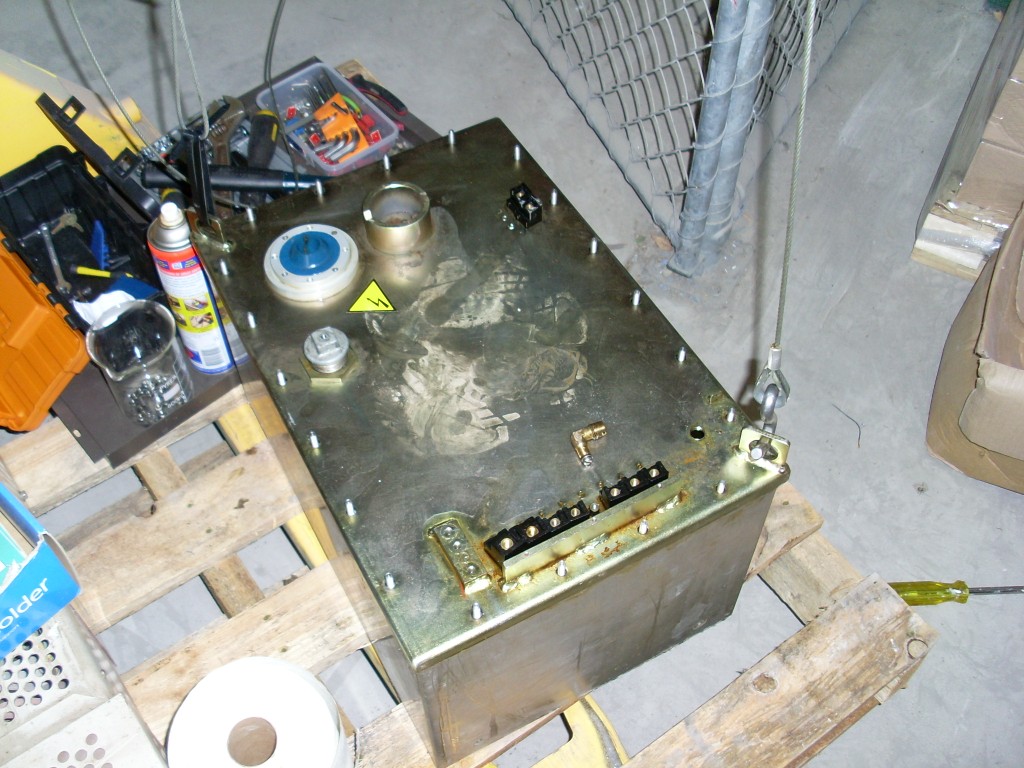
    X-ray unit tank circuit


    This thing is heavy!
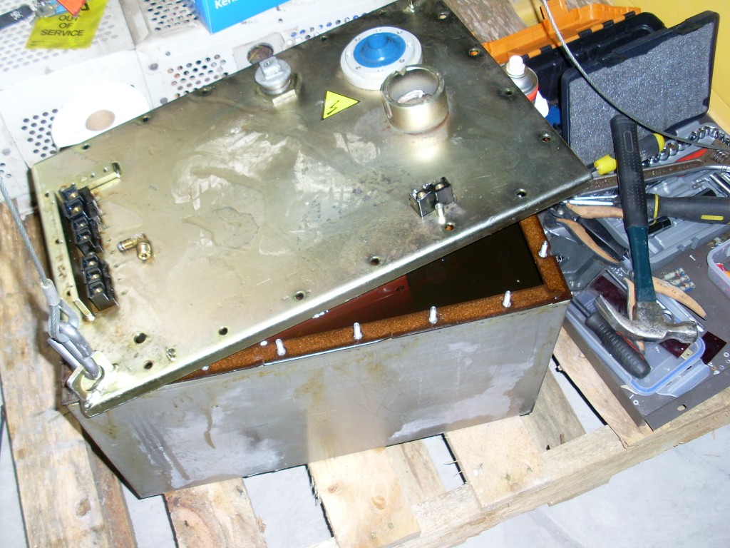


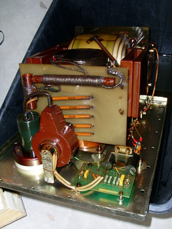
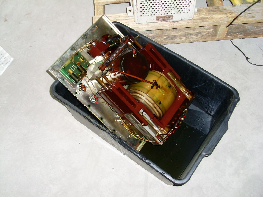
    Cracked it! No wonder its heavy, the transformer is mounted under the lid.
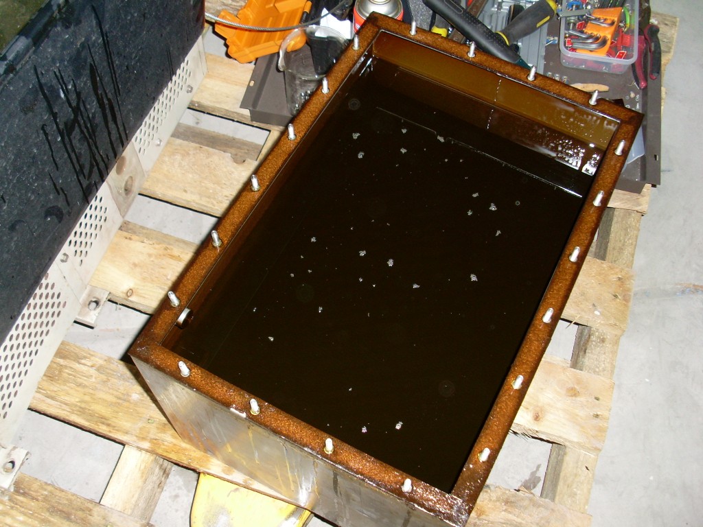


    Yummy transformer oil.
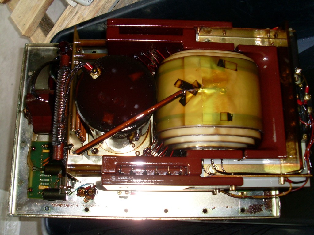
    "Doesn't matter how many times you kick the coyote in the head, it's still gonna eat chickens". - EPD

  • #2

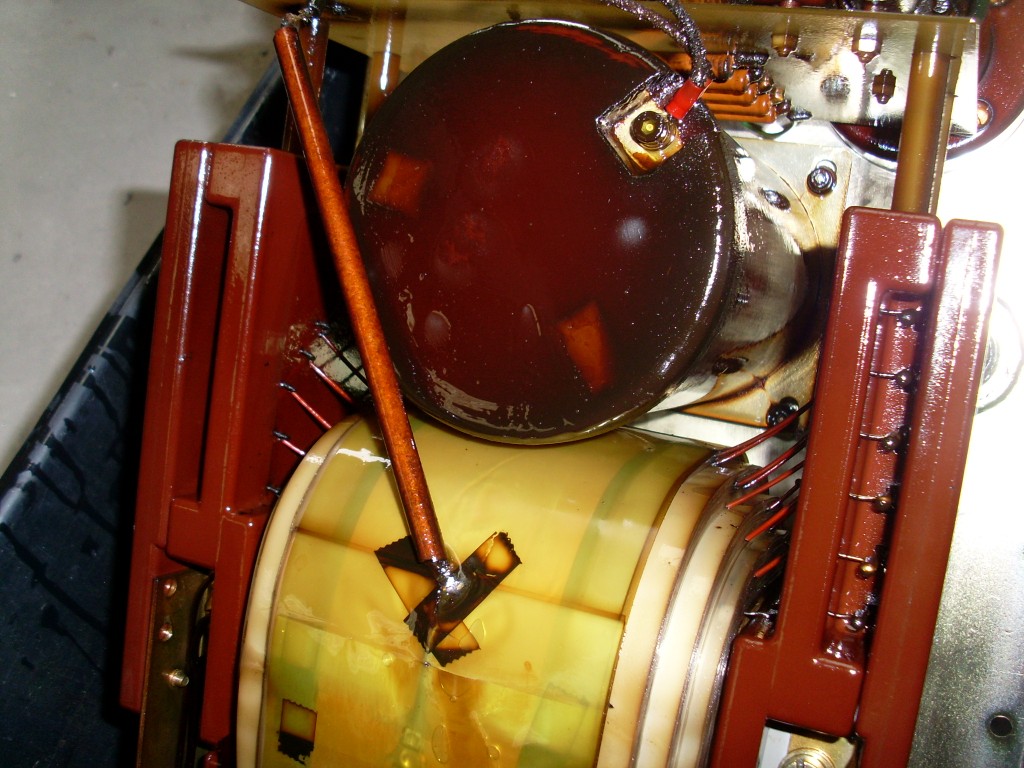
    The underside. Big transformer. Go on, study those windings? I think I see one fault, the tube broken off from transformer winding the inductor. Everything is brittle, looks like it got slightly warm at one point.


    25M resistors can be seen, with a HV filament transformer in the foreground


    Overall underside view.

    More later
    Sputins
    Last edited by Sputins; 10-16-2014, 06:02 AM.
    "Doesn't matter how many times you kick the coyote in the head, it's still gonna eat chickens". - EPD

    Comment


    • #3
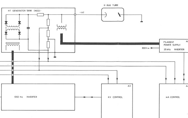
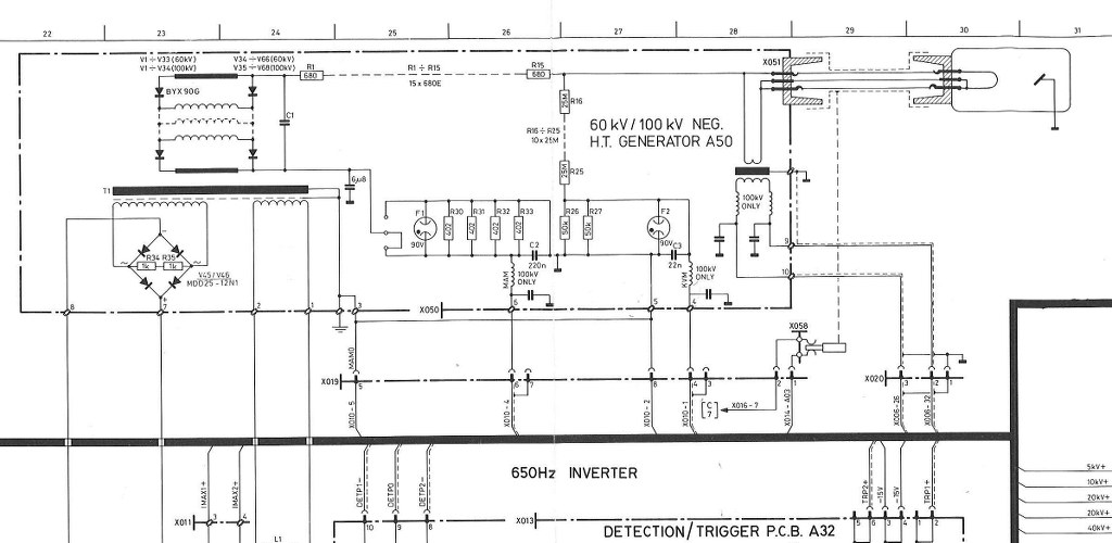
      Schematic - part2


      Block diagram of tank [simple]


      Schematic: [well kind of]
      "Doesn't matter how many times you kick the coyote in the head, it's still gonna eat chickens". - EPD

      Comment


      • #4
        Only fascinating!

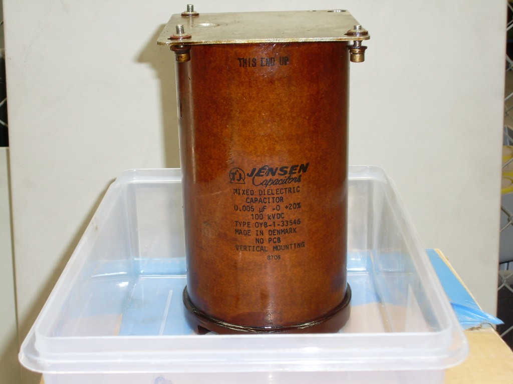
        Would those capacitors have been a 'standard' (albeit very expensive) part, or would they have been custom-made for these x-ray machines?

        Comment


        • #5
          Originally posted by sprocket View Post
          Only fascinating!

          Would those capacitors have been a 'standard' (albeit very expensive) part, or would they have been custom-made for these x-ray machines?
          "Doesn't matter how many times you kick the coyote in the head, it's still gonna eat chickens". - EPD

          Comment

          Working...
          X