This forum is preserved as a permanent archive. The community continues at eMedia Press.

Announcement

Collapse
No announcement yet.

invert a signal to mosfet

Collapse
X
 
  • Filter
  • Time
  • Show
Clear All
new posts

  • invert a signal to mosfet

    Hi all, i need a little help with a circuit.

    I already successfully have my function generator triggering a mosfet to turn on & off... what i also want is to at the same time invert the signal from the function generator and send to another mosfet.....so that both mosfets are flip-flopping at the frequency set by the function generator.

    anybody help with this?

    thanks,

    David. D

  • #2
    Hi,

    Do you mean when one of the MOSFETs are ON from the pulse then the other MOSFET should be OFF?

    If yes, you can use a simple CMOS inverter like a CD4049 or CD40106.

    They invert a pulse, when the pulse is ON, it has say 5V peak amplitude and you input it to an inverter gate like CD40106 the output of the gate will be at low level (< .5-1V instead of the 5V) and when the original pulse id at low level then the output of the inverter gate will be at a high level. Is this what you need?

    rgds, Gyula

    Comment


    • #3
      yes gyula......i want......when one mosfet is ON......i want the other mosfet to be OFF....and vice-versa.........my mosfets seem to require about at least 9 volts or so to turn on though

      my function gen can output 20 volts peak-to-peak

      Comment


      • #4
        Ok, the CMOS digital logic family works any DC supply voltage from 3V to 15V or so. I think you could download a PDF file from overunity.com which includes a schematic on such inverting gate circuits like the CD40106, here is the link:

        Login file title is Simple_Cheap_Low_Power_Oscillators_2.0.pdf written by poyint9.

        see page 4 in the pdf file, it includes a pulse oscillator too but you do not need that if wish to use the function generator, you can drive the gates directly from your generator. For instance you drive pin 9 of U1D directly from the gen and its pin 8 output can drive one MOSFET gate, and output pin 10 of U1E can drive directly the other MOSFET gate with the INVERTED pulse. This way when one FET is ON, the other is OFF and vice versa. (Both FETs are supposed to be N channel types, right?)

        Important: if you use say 12V DC supply voltage for the CD40106, and you wish to drive it from your pulse generator, then the output level of the gen can be only a maximum of 12V peak to peak, ok? Do NOT drive the IC with 20V output pulse. Maximum DC supply is about 15V for the IC and if you use 15V, then you may increase the pulse output level of the generator up to also 15V peak to peak, ok?

        The CD40106 includes 6 Schmitt inverting gates, with common supply pins, you can use any one or two of them, what is more you can connect any input and output in parallel with each other to increase driving current capability to the MOSFET gates. I mean for instance 3 Schmitt gates in parallel drive one FET and the other three Schmitt gates in parallel would drive the other FET directly.
        If you use only one Schmitt gate for inverting the generator pulse, of course you can, but then all the other 5 unused Schmitt gate input pins should be connected to the positive supply rail (or to the GND) like as shown with pin13 of U1F because U1F is not used. This is CMOS IC rule. Then the Schmitt gates output pins can be left unconnected.
        Hope these are of help.

        rgds, Gyula
        Last edited by gyula; 07-14-2010, 09:21 AM.

        Comment


        • #5
          Gyula,

          thanks a lot, that sounds like a nice neat solution to what i want.

          checking for the pdf now

          Comment


          • #6
            wow..just checked my components boxes.....and found...a CD40106B ! ( must have bought it ages ago and forgot about it...not that i even knew what the hell to do with it back then.....but i doooooo nowww )

            Comment


            • #7
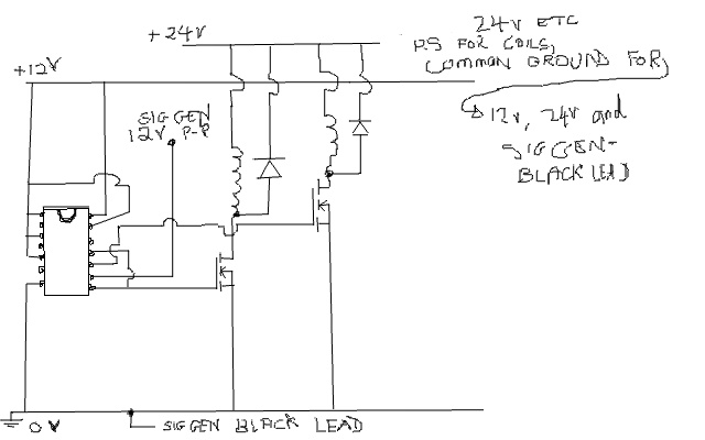
              gyula check before wiring

              Hi, gyula, if you could........could you check the attachment for my wiring, i think its correct.

              thanks a LOT
              Attached Files

              Comment


              • #8
                Hi David,

                Yes it seems ok. Go ahead.

                Gyula

                Comment


                • #9
                  thanks....on it

                  Comment


                  • #10
                    gyula....

                    put 2 bulbs, one on each mosfet, frequency at 1 Hz....IT WORKS !!! ( youre a genius ).....

                    so i have a $300 function gen, driving a cmos chip, driving two high power mosfets, driving two bulbs...i have the worlds most expensive christmas tree lights !!

                    Thank you Very much........now i can do alllllllll those flip-flop experiments with coils and of course my rodin coils that i always wanted to do but wasnt able to......if i can even remember what they were by this time

                    great little chip this 40106.....ordered 3 more

                    thanks a bunch, this REALLY helped and saved me a lot of headaches

                    Comment


                    • #11
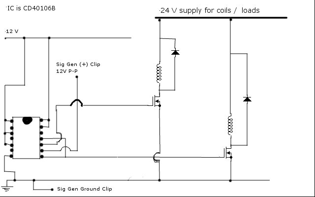
                      circuit

                      here attatched is a cleaner version of the circuit
                      Attached Files

                      Comment


                      • #12
                        Originally posted by rave154 View Post
                        gyula....

                        put 2 bulbs, one on each mosfet, frequency at 1 Hz....IT WORKS !!! ( youre a genius ).....

                        so i have a $300 function gen, driving a cmos chip, driving two high power mosfets, driving two bulbs...i have the worlds most expensive christmas tree lights !!

                        Thank you Very much........now i can do alllllllll those flip-flop experiments with coils and of course my rodin coils that i always wanted to do but wasnt able to......if i can even remember what they were by this time

                        great little chip this 40106.....ordered 3 more

                        thanks a bunch, this REALLY helped and saved me a lot of headaches
                        I am pleased you have made it work as you wished it to work.

                        Later you can consider that there are 5 additional Schmitt trigger gates in one 40106 package you do not use now, one possible usage for them is to connect them in parallel so that their output current driving the MOSFET gates-source should increase, this can help achieve more rapid switching times for the MOSFETs. For Christmas tree lighting this may not be important but it may be for other coils switching.
                        To parallel them, you simply connect inputs together directly and you also connect the corresponding outputs together, to get one common input and one common output from any number of Schmitt gates.

                        rgds, Gyula

                        Comment


                        • #13
                          Are mosfets not voltage driven. The higher the better for driving coils?

                          Comment


                          • #14
                            Their working principle makes them voltage driven devices indeed, however in practice they have a significant input capacitance between their gate and source electrodes, (for power MOSFETs this is in the some nanoFarad range) and to utilize their quick switching speed the input capacitance should be charged up and then discharged also very quickly (in some ten nanosecond).
                            This process inherently needs current (any capacitor takes current to charge and then in case of the MOSFET input capacitance you have to discharge it also quickly: this is loss) hence the input power need is established... especially that the control voltage should be in the 10V range at least (as you say the higher the better for coils), and can go up to 20V or so.

                            Comment


                            • #15
                              How do we discharge the capacitance quickly at switch off?

                              Comment

                              Working...
                              X