-
-
The Swinging Gym posted by Rickoff:
YouTube - Dennis Barber Swinging Gyms Hanbury Steam Rally Stoke Prior Fair 19th September 2009 -
An ingenious idea indeed, and very nice schematics.
In picture 3, will the stator magnet not also slow down the rotational speed of the swing?
If you find any situation where you can use permanent magnets to input more potential (height) energy than it extracts kinetic energy, you have passed the OU threshold. Hundreds of researchers will build your design.Comment
-
Hi David,
I have done some testing of similar ideas on my bike wheel set up, with little success, but time spent was enjoyable just the same. I could never avoid the sticky spot
 at the point of change from attraction to repulsion, although my wheel was rotating in a horizontal plane at the time and not taking advantage of any gravitational assist. In looking at your drawings two things come to mind.
1- you have a large imbalance, which I'm sure gravity would like, but bearings maybe not so much. Perhaps not as much imbalance is needed and might be accomplished by adding a second spoke opposing the first. The two sliding P-magnets could be connected by a rod and would be working together.
2- Now this one may be way out there, for I have very little electrical knowledge, and would very much complicate the build. But perhaps someone here could set me straight on this, for there are many bright thinkers here. I see in a two spoke set up, sliding magnets moving four times in each revolution. Now here is the big IF, if these magnets were sliding inside a coil might a electrical pulse be produced, stored in a capacitor, and dumped to a solenoid to some how assist in getting past the sticky spot?
Best to you, Gene
(Thinker + Tinker + F.E.)
Comment
-
Hi Cloxxki:Originally posted by gene gene View Post
I will be happy if any of my ideas will do well to the world.
I hope that will accelerate up and pump it, instead of braking the rpm.
Only a prototype will show that.
Gene:
Attraction on the downside where gravity works will reduce acceleration.
I am showing one arm but we can put as many spokes as you can between the rim and axle.
Connecting the arms may work. Attached is a picture with the idea.
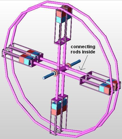
We can even double the spokes, side by side and connect tem thru the inside of the arms. I am working on a drawing.
David
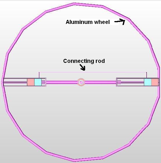 Last edited by Matos de Matos; 07-15-2010, 01:52 PM.
Comment
-
The setup showed with multiple spokes and rod connecting sliding magnets inside the arm.
Comment
-
The repulsion field closer to the sliding magnet and at contact, with a weaker field. This may reduce damping.

Comment
-
There are 3 problems with this concept that would need to be overcome for it to function. However, they are not insurmountable.
1. At the top of travel, the magnet used to provide the lift will also tend to attract the rotor and absorb its momentum by applying negative torque as the rotor magnet leaves it's proximity.
2. At the bottom, there is an opposing field that applies negative torque similar to #1 above, but for opposite reasons.
3. Aluminum rails will hamper rotor magnet motion due to inductance.
It is possible to pit the magnetic field and gravitational fields against each other to get a gain. See YouTube - AdminOnDuty's Channel
and FizzX.org :: View topic - Magnetically Assisted Pendulum for more info."Amy Pond, there is something you need to understand, and someday your life may depend on it: I am definitely a madman with a box." ~The DoctorComment

This forum is preserved as a permanent archive. The community continues at eMedia Press.
- If this is your first visit, be sure to check out the FAQ by clicking the link above. You may have to register before you can post: click the register link above to proceed. To start viewing messages, select the forum that you want to visit from the selection below.

 Tweet
Tweet
Comment