This forum is preserved as a permanent archive. The community continues at eMedia Press.

Announcement

Collapse
No announcement yet.

Tesla Magnifying Transmitter/Eric Dollard Type Coils Compendium

Collapse
X
 
  • Filter
  • Time
  • Show
Clear All
new posts

  • Tesla Magnifying Transmitter/Eric Dollard Type Coils Compendium

    This thread is for data and results derived from TMT/EPD/CRI type coils, including US Patent 1119732

    Patent US1119732 - ELECTRICAL ENERGY - Google Patents

    -----

    Originally posted by T-rex
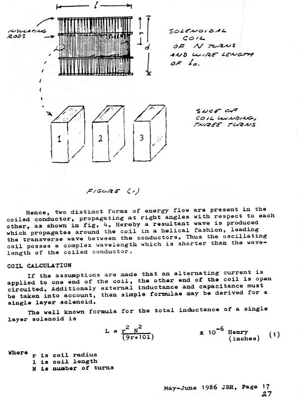
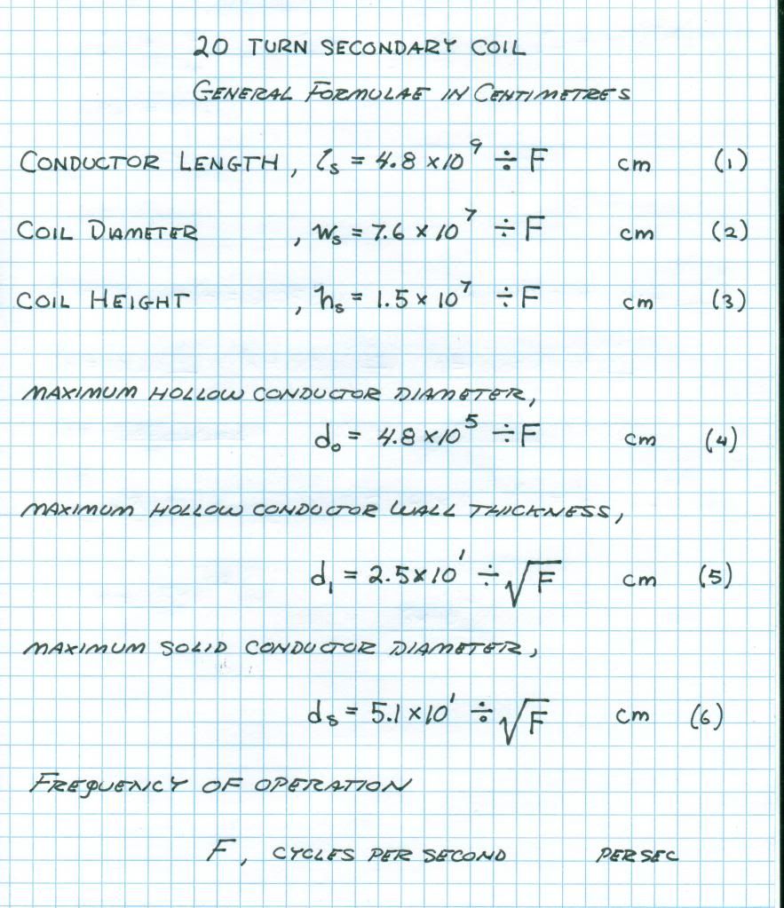
    All equations here will work with everyone's coils. They have been tested experimentally and are known to work.


    On this last page the values listed in table 3 are wrong. They need to be recalculated from the equations in the text.
    -----

    Originally posted by T-rex
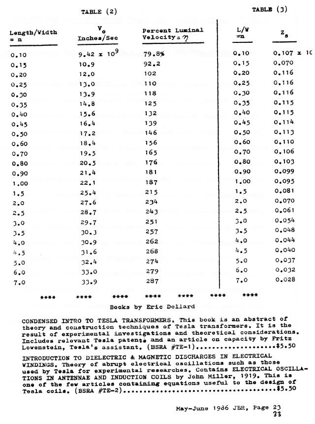
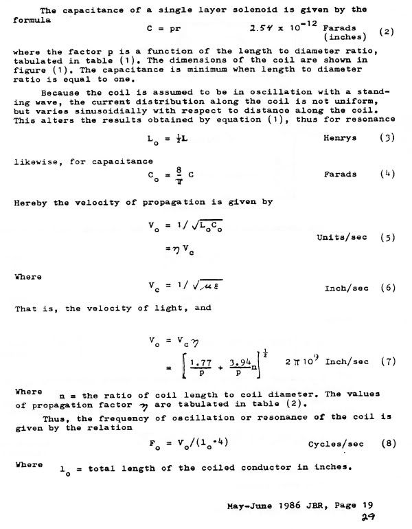
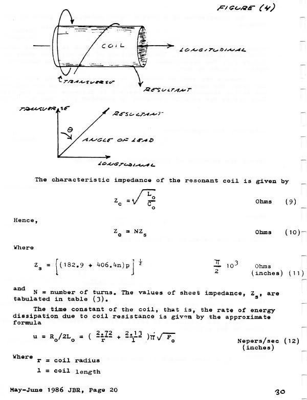
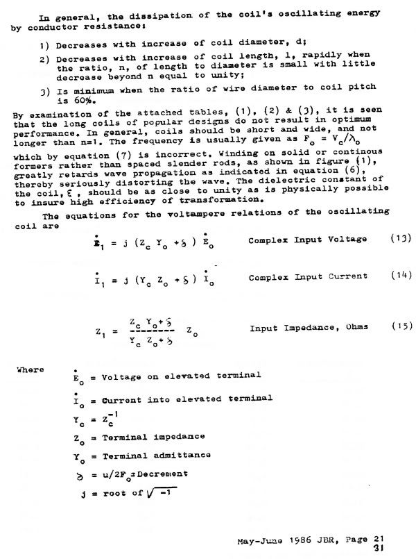
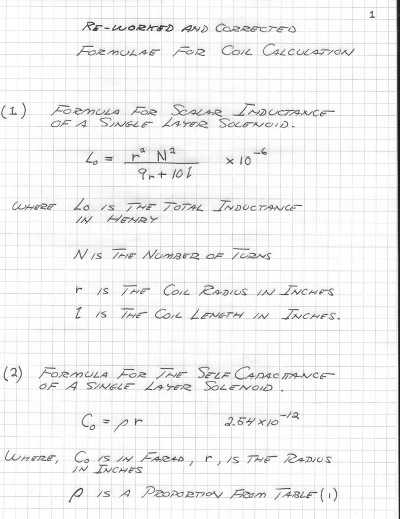
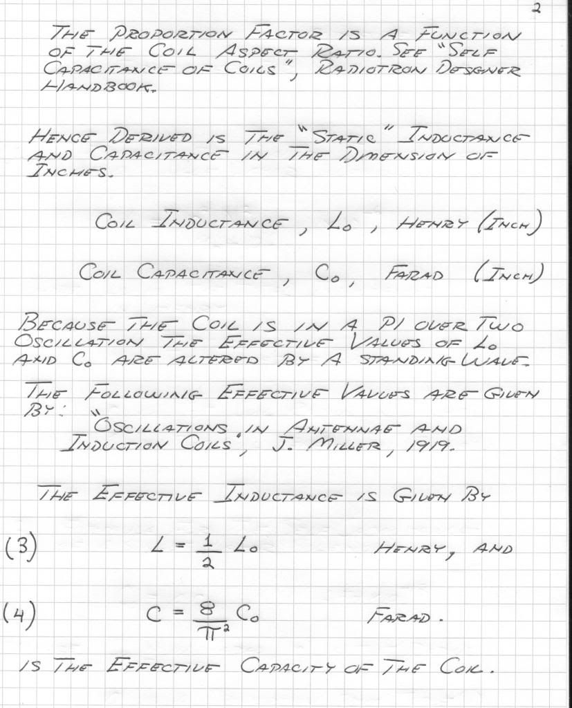
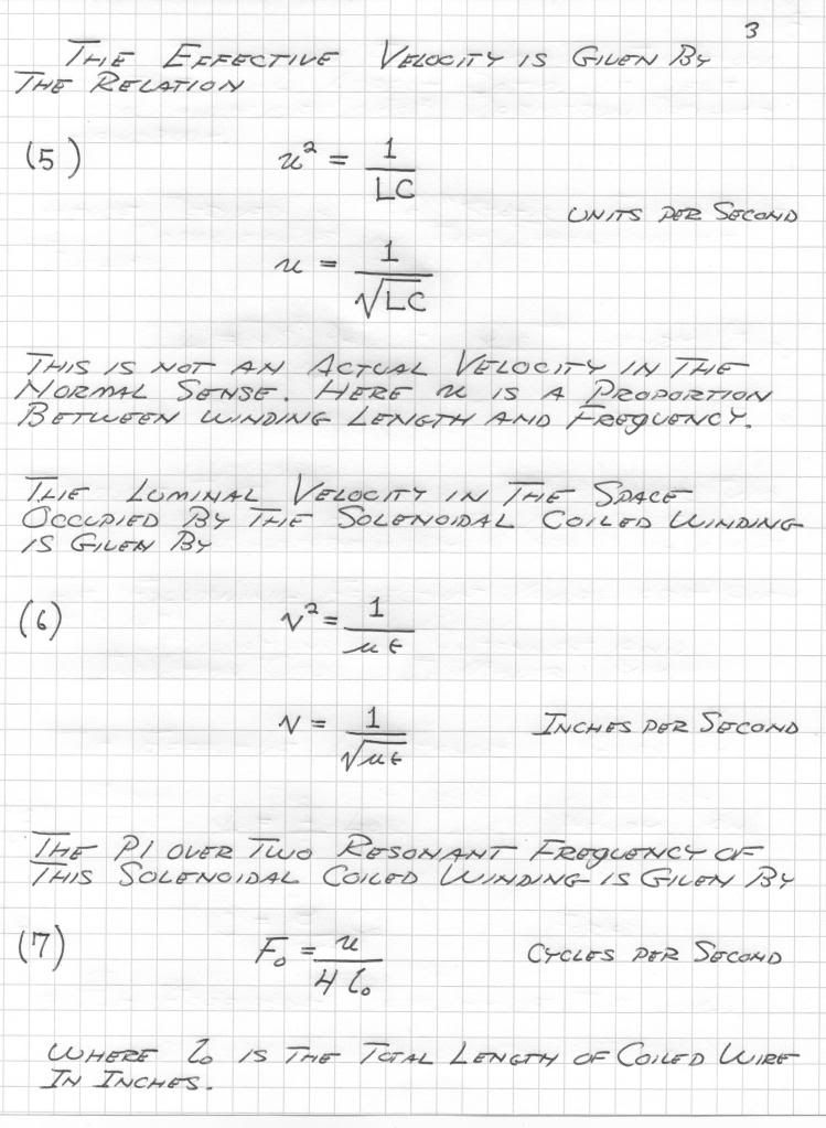
    The following is the corrected version of the equations given. Equations (1) and (2) still need to be substituted into equations (6), (7), and (9).


    Originally posted by T-rex
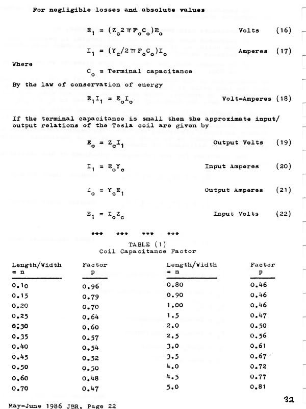
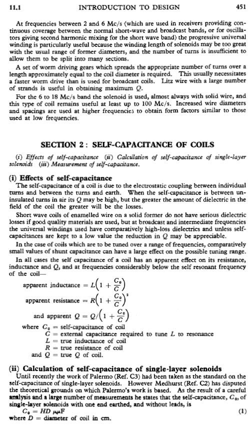
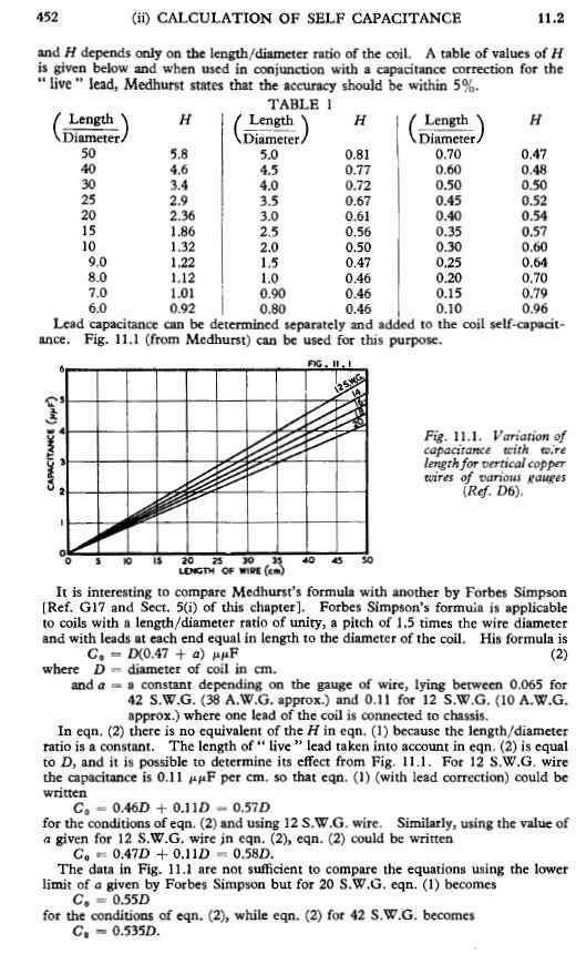
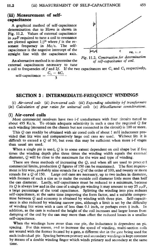
    From Radiotron Designers Handbook


    Last edited by dR-Green; 07-26-2012, 10:03 AM.
    http://www.teslascientific.com/

    "Knowledge is cosmic. It does not evolve or unfold in man. Man unfolds to an awareness of it. He gradually discovers it." - Walter Russell

    "Once men died for Truth, but now Truth dies at the hands of men." - Manly P. Hall

  • #2
    ..........
    http://www.teslascientific.com/

    "Knowledge is cosmic. It does not evolve or unfold in man. Man unfolds to an awareness of it. He gradually discovers it." - Walter Russell

    "Once men died for Truth, but now Truth dies at the hands of men." - Manly P. Hall

    Comment


    • #3


      For new extra coil wire length refer to July 2 2012 note


      Originally posted by Geometric_Algebra
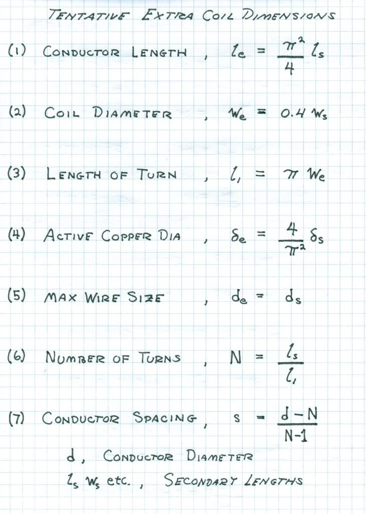
      Here's the clarifications on the factor (pi^2/4) and tips on coil design that Eric has provided me:

      There should not be much left unanswered, it is all in the "Theory of Wireless Power" and "Impulses, Waves and Discharges." But all of this pre-supposes a working knowledge of radio frequency lines and antennae.

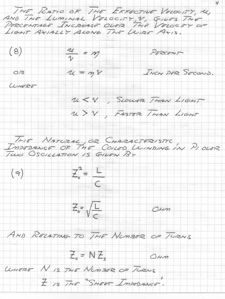
      Velocity depends on aspect ratio. If Secondary ratio is 18%, velocity is luminal, this only at 18%. So make the coil 20% and the velocity is a bit faster than luminal. The reason, to compensate for the slowing caused by insulation.

      The secondary is coupled to other coils and capacitance. This lowers the velocity greatly. Thus to compensate the coil wire is shortened by 2/pi=0.63662=63.7% to bring the frequency back up to the proper value.

      As for the extra coil; for a coil aspect ratio of 100% the coil effective velocity is 187% that of luminal velocity (along the coil wire). This coil is burdened down by insulation and gradient rings as well as what little coupling Exists. Thus the coil Wire is lengthened to 157% velocity factor. This is to say, rather than calculating the extra coil on a velocity of 187% that of light along the coil wire to figure the quarter wave, we now instead, in order to compensate for the burden, use a velocity of 157% that of light along the coil wire to figure quarter wave. 157% is equal to pi/2.

      Therefore, secondary 2/pi, extra coil pi/2.

      (Longer Extra)/(Shorter Sec.) = (pi/2)/(2/pi)=pi^2/4=2.465

      Where pi is a correction factor, not an intrinsic mathematical relation. But it may be that by using pi some "magic" resonance may take form. (Experiment and see).

      Also important in the use of gradient rings at coil ends. These are like capacitors and keep losses low by not stressing insulation with flux concentrations. Quarter inch copper tubing fine. It must be slotted so as not to be a shorted turn! Connect end wire of coil to ring, it is a final turn.

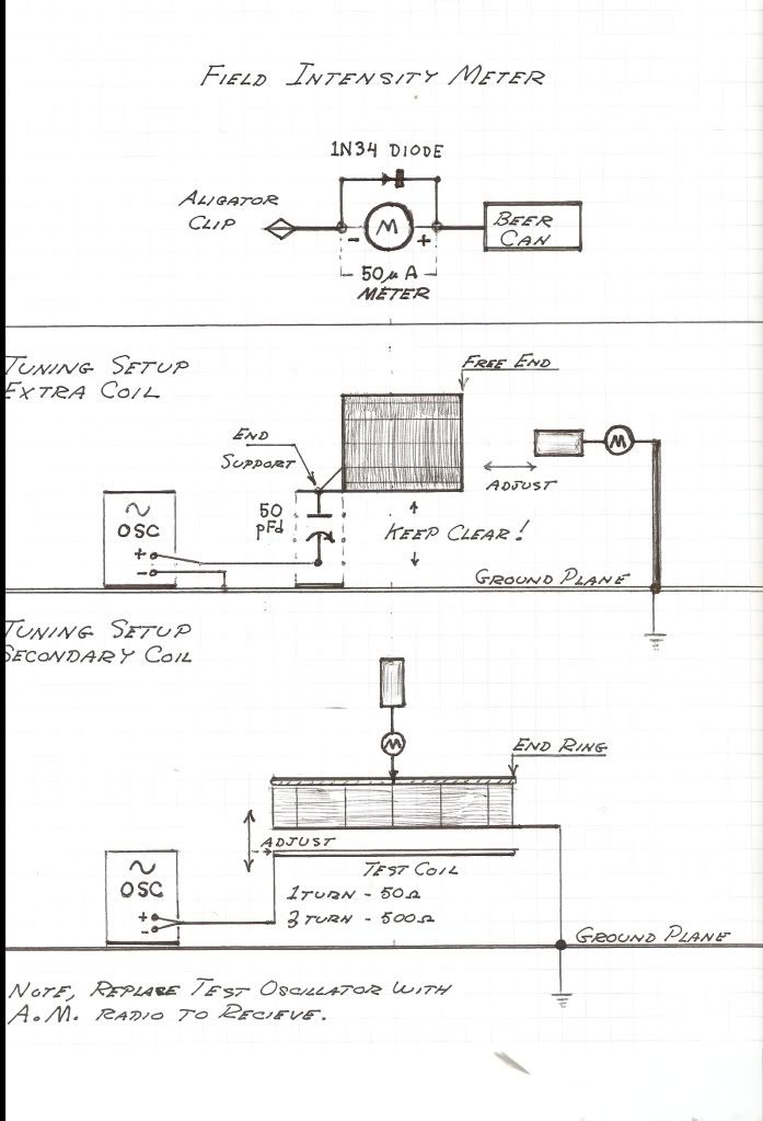
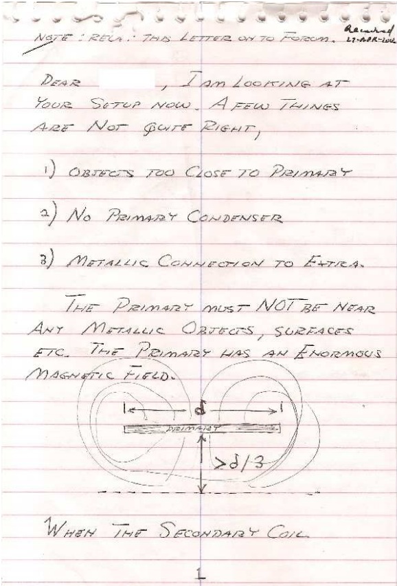
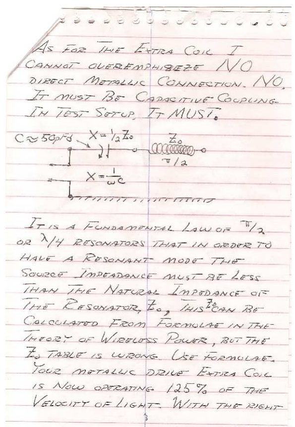
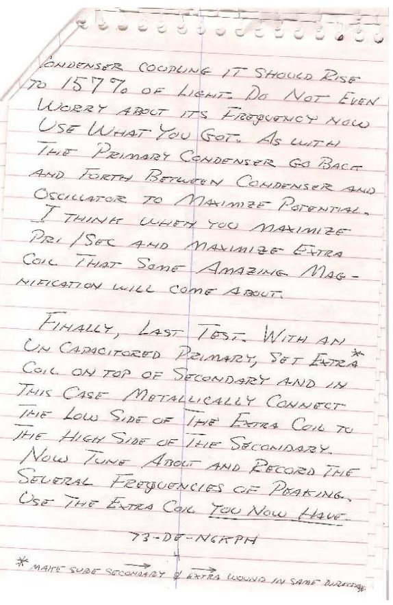
      Also, tuning a coupled extra and secondary coil is an effort for the master, not the novice thus all effort must go into the secondary coil and its primary coupled resonator, or primary coil-condenser structure. No connection must exist between coils, None! No test leads should contact coils, No Leads! Electro-static coupling or magnetic loop coupling to meters is all that is permissible. Extra coil must be as free as possible. Then it can really "take off." But tuning and loose coupling factors will be very difficult and resonance will be elusively sharp.

      Where it is that the teflon coating on the wire is important for gradient control on wire, any and all insulation impairs resonance. It must actually be an "air" wound coil. This cannot be overly emphisized. The only proper way is to construct a coil such: cut two circular rings out of wood/plastic sheets. Drill eight holes equidistant in these rings to press fit coil support rods (broom sticks) press together rings and rods into former, notch rods to hold coil turns in place. Nothing can be more simple than this, and the losses and burdens are greatly minimized by the construction. All wood parts must be baked dry, varnished, and re-baked. Good Rod Material is lexan, glass Epoxy, Plexiglass, and Baked wood is o.k. The skiny rod is better than a fat rod. Hollow rods even better. Notches hold wires and varnish them in place.

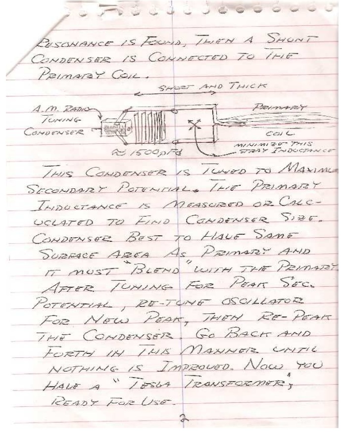
      Any old vacuum tube A.M. radio is a good thing to use here. But don't let a hot chassis kill you! Get an isolation transformer. Radio has an oscillator in it for making a test V.F.O. Also that big spider loop on back can be coupled to Tesla unit so then one can listen to radio to hear the resonant boost. A.M. car radios are electro-static so whip can be near gradient ring for pickup. (Loopsticks are magnetic).

      Finally, a ground plane is a must. Ground wires greatly detune the system, so one foot maximum neutral to ground wire length. A 6 by 6 foot aluminum foil sandwich of wood and an aluminum slide between is the minimum area and connect to it. Run ground wires to earth off of four corners. Use four separate groundings like four different outlets, or bathroom/kitchen plumbing etc. Spread it out! (Surfaces) [image, not shown here, depicts grounding in four corners of table plate, and neutral coil connection in center of plate.]


      Originally posted by Geometric_Algebra
      Rewritten notes from Eric on a technique for coil node detection.

      June 23 2012

      Originally posted by T-rex
      The extra coil raising the resonant frequency of the resonant transformer(Pri + Sec) is great. This is what I am looking for. This result means that the extra coil is exhibiting an inductive reactance, indicating its operation is a little beyond its quarter wave frequency. The shunt ring capacitor exists to tune this magnetic component out. Thereby derived is a condition of consonant resonance which both secondary and extra coils are in tune.

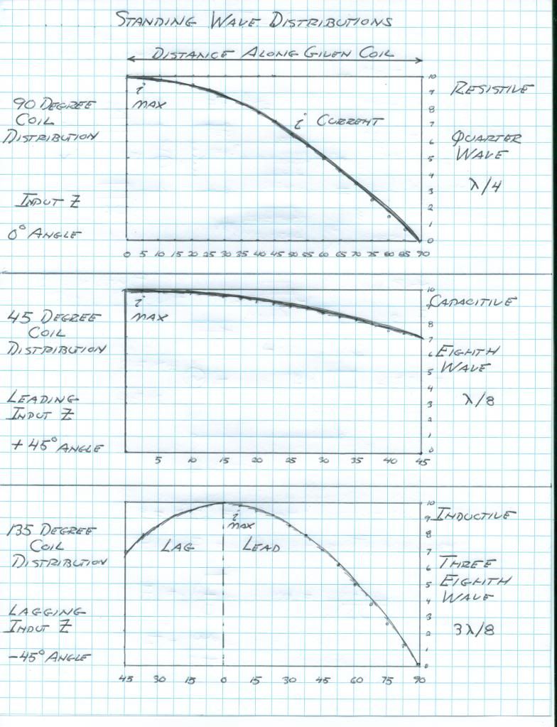
      Also, do not use L.E.D. use small incandescent lamps like the #327, #44, or #42 number lamps. Use Ne2H lamps as the voltage probes, a neon wire lead lamp on the end of a stick. The coils need to be supplied with enough power to light a neon lamp along the coil. Also, the tiny incandescent lamp with an exploring coil is a good M.M.F. probe. With these the standing wave distribution can be studied on these coils.

      In basic terms, if a transmission structure can support travelling and standing waves, a set of relations exist.

      1) If the line is quarter wave resonant, the sending impedance is resistive, at the resonant frequency.

      2) If the line is operated at a frequency of less than that of the quarter wave frequency, the sending end impedance is capacitive.

      3) If the line is operated at a frequency higher than the quarter wave resonant frequency, the sending end of the line is inductive.

      4) In order to establish a quarter wave resonance, this within an eighth wave up, or down, span of frequencies around this resonant frequency, two conditions must be met.

      One is that the sending end impedance must be LESS than the characteristic impedance of the line.

      Second is that the far end impedance must be greater than the characteristic impedance of the line. This is to say, the far end admittance must be less than the characteristic admittance of the line.

      When a line is operated at an eighth wavelength it has the property of converting the far end impedance to a resistance equaling the magnitude of the far end impedance, this at the sending end of the line. Marconi used this in his flat top at KET Bolinas, and to a certain extent this may be happening in the Colorado Springs extra coil, but only if expressed in a luminal velocity base. Read Steinmetz, "Oscillations of the Compound Circuit", in "Impulses, Waves, and Discharges", very important info on the refraction and reflection of waves at the transition between two independent transmission structures (or coils).

      June 27 2012

      Originally posted by T-rex
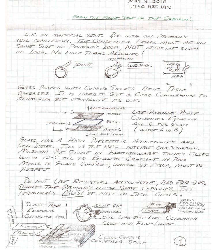
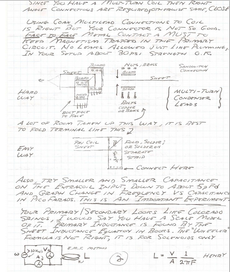
      The secondary winding is the prime mover of this transformer. Here the system operating frequency is established , and then locked in place by a primary resonator. This in itself establishes a telluric transmission network, a basic resonant transformer with a mono-polar connection at the secondary neutral. Another transformer can be constructed, identical in every way except wound in an opposite direction to the first coil. Interlinking the neutrals of these two counter-wound transformers enables a one wire transmission between the two units. This is the basic telluric system. No more is needed than this.

      The extra coil is employed in order to magnify the potential to much higher values than possible with only a secondary winding*. This however involves ratios of refractions and reflection that are difficult to calculate or even understand. Hence its complications are best avoided in basic telluric testing.

      *This will increase receiving sensitivity, or "gain"

      Two modes are possible for extra coil in relation with the secondary coil. Both involve quarter wave resonant rise, this the fundamental of resonant transformation. Its also known as constant potential to constant current transformation. A constant potential is a zero impedance (short circuit) a constant current is a zero admittance (open circuit). Departure from these zero values alters the coil distribution to something other than a quarter wave.

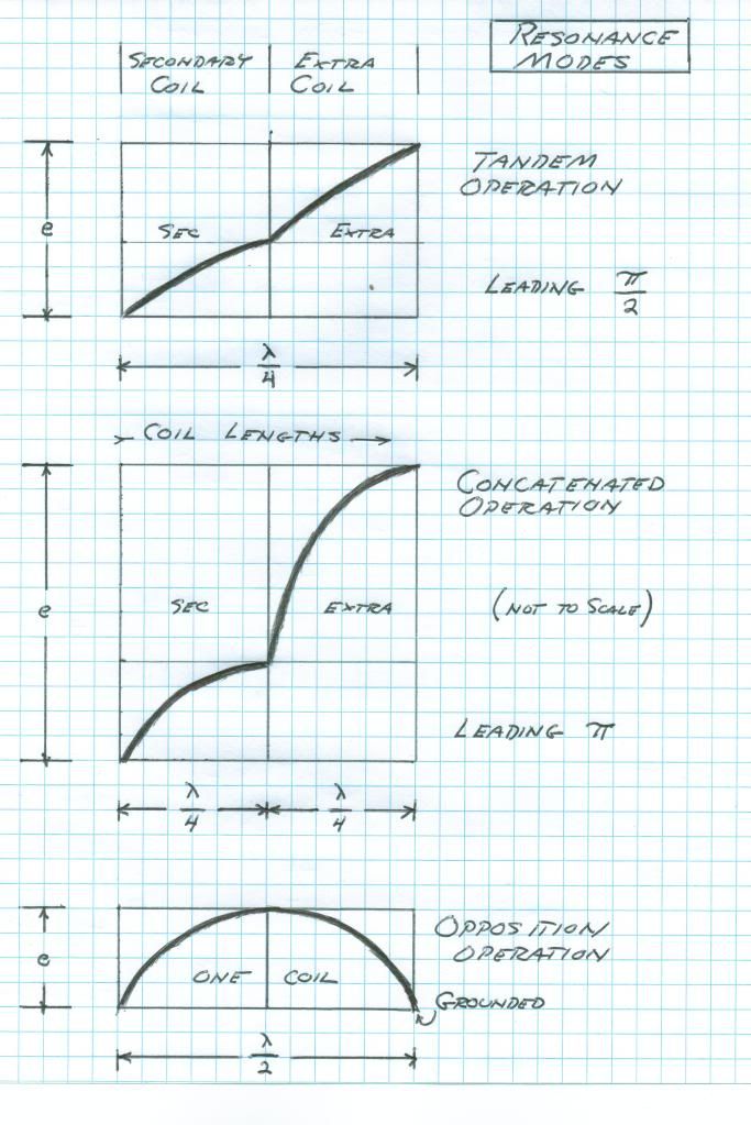
      This quarter wave can exist in a distinct pair of manifestations. The first mode is when the quarter wave is distributed over the length of both extra and secondary windings as a whole, a pair of eighth waves let us say. This is the TANDEM mode. A multiplication in potential is derived hereby since the extra coil exhibits a higher transmission impedance thereby giving rise to a greater EMF between turns and thus a higher termination potential. All photos of my Bolinas and Integratron setups operated in this mode. It is the easy one to achieve.

      The second mode of the extra coil and secondary coil connection involves two quarter wave distributions, one on each coil. This is not to be considered a half wave however. This mode is the CONCATENATED connection.It compounds the quarter wave resonant rise of the secondary coil with another quarter wave rise in the extra coil, hence a concatenated resonant rise. This is the holy grail of resonant transformer design and unheard of potentials may be gained in this manner. To derive this analytically is extremely difficult, it is an advance transmission line problem. It might not even be possible to calculate or even achieve this mode of resonance, but we are going to give it a try. Tesla dreamed of this mode but electrical knowledge was in its infancy in Tesla's Colorado years.


      An excellent addendum to this is the John Miller Paper "Electrical Oscillations in Antennae and Induction Coils" provided with Eric Dollard's paper "Introduction to Dielectric and Magnetic Discharges in Electrical Windings". It can be seen here:

      http://www.tuks.nl/pdf/Eric_Dollard_...0remake%29.pdf
      Last edited by dR-Green; 07-27-2012, 12:28 AM.
      http://www.teslascientific.com/

      "Knowledge is cosmic. It does not evolve or unfold in man. Man unfolds to an awareness of it. He gradually discovers it." - Walter Russell

      "Once men died for Truth, but now Truth dies at the hands of men." - Manly P. Hall

      Comment


      • #4
        From the ARRL Antenna Book:


        -----


        Test Coil = 1 turn 1.5mm wire

        F = 3670000 cycles/sec

        Secondary Coil:
        20 turns
        Diameter = 20.7cm
        Height = 4.08cm
        Conductor length = 13.079 metres

        Luminal frequency = 5730.4 kc
        Free maximum frequency = 4126 kc - Magnification Factor = 63.70233
        Rings = 3670 kc - Magnification Factor = 83.71159

        Extra Coil:
        126 turns
        Diameter = 8.28cm
        Height = 8.28cm
        Conductor length = 32.271 metres

        Luminal frequency = 2322.4 kc
        Direct = 2694.8 kc - Magnification Factor = 57.07992
        10pF = 2833.1 kc - Magnification Factor = 81.5891

        Concatenated Coils:
        First Peak Resonance: 3670 kc
        Second Peak Resonance: 2340 kc


        Originally posted by T-rex
        Consideration of Coil Self Capacitance
        1) Extra Coil Diameter
        8.25 cm

        2) Capacitance factor from Radiotron table for a coil aspect ratio of 100%
        .46 Numeric

        3) Multiply this by the coil diameter
        3.8 picofarads

        4) This is the "free space" self capacitance of this extra coil. This means a true air wound coil.

        Now to determine the actual working capacitance of this extra coil resulting from the coil form and stray lead parasitic capacitance.

        1) The theoretical velocity factor from the Wireless Power Table for a coil with a 100% aspect ratio:
        187% numeric

        2) The actual measured velocity factor
        124% numeric

        3) Taking the ratio of the free space to actual measured velocity gives
        1.51 numeric

        Note, close to 1.54, pi/2

        4) Velocity varies as the inverse of the square root of the capacitance
        2.28 numeric

        5) Multiplication of the free space capacitance by this squared factor
        8.7 picofarads

        6) This is the burdened coil capacitance resulting from the coil form and connecting leads.

        Observe that the 45 degree knee or asymptote point is this derived value of capacitance. This effective coil capacitance is the square root of its self capacitance, C and its mutual elastance, K.

        Dr Green #396 (II)

        Considerations of the magnification factor as derived from the bandwidth of the resonance curve, this the half power, or 71% voltage points on the curve.

        1) Determine the 71% points on the extra coil curve (for 10 pFd).

        Lower Sideband Point
        2821 Kilocycles/sec

        Upper Sideband Point
        2831 Kilocycles/sec

        Hence the half power bandpass is 17 Kilocycles or 6%

        2) Two factors are here derived. Factor d is the ratio of the bandwidth to the center frequency, 2830 Kc/sec.
        0.006

        Factor n is the inverse of factor d:
        167

        3) Here derived is the magnification factor of this extra coil,
        n = 167 numeric

        General Conclusions

        This extra coil is now quantified as to its general electrical behavior:

        v = 124% luminal velocity
        C = 8.7 pico
        Farad
        n = x 167 magnification factor
        Originally posted by T-rex
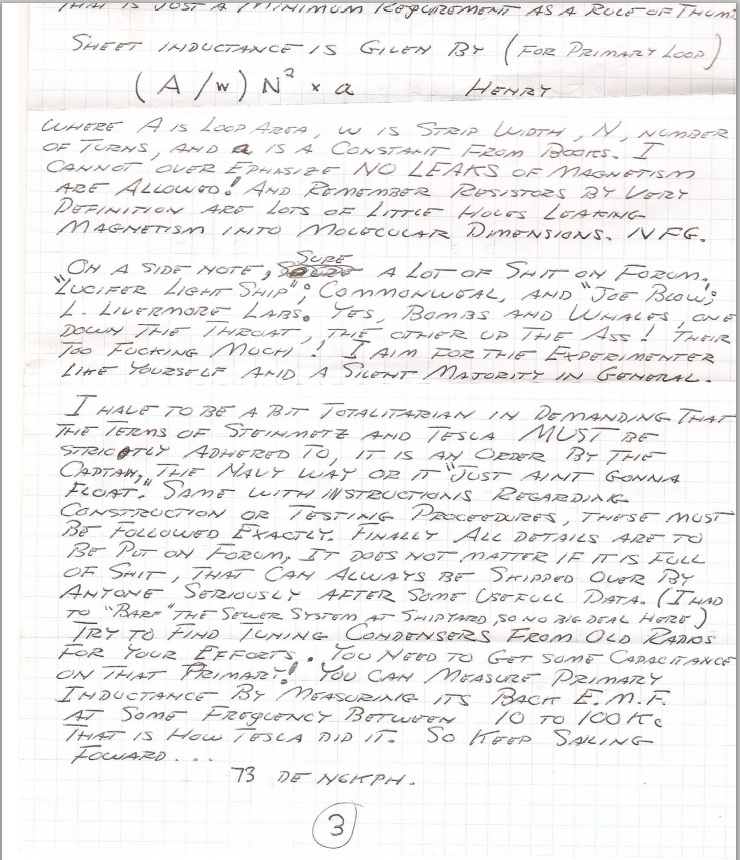
        The inductance, characteristic impedance and resonant frequency of this extra coil is now developed.

        1) The magnetic inductance of the extra coil by Wheeler's formula (Theory of Wireless Power) is
        846 microHenry

        2) The effective inductance for a cosine quarter wavelength current distribution is

        by Steinmetz, two over Pi the total inductance,
        539 microHenry

        By Miller, one half the total inductance,
        423 microHenry

        3) The equivalent capacitance of the extra coil is given as
        8.7 picoFarad

        4) The effective capacitance for a sine quarter wave distribution is

        by Steinmetz, two over Pi times C,
        5.5 picoFarads

        by Miller, eight over Pi squared times C,
        7.1 picoFarads

        4)The Characteristic coil impedance is defined as the square root of the ratio of inductance to capacitance

        By Steinmetz
        9.9 Kilo Ohm

        by Miller
        7.7 Kilo Ohm

        5) The angular frequency is defined as the inverse of the square root of the product of inductance and capacitance

        18 Kilo-radians per second
        or
        2860 Kilocycles/sec

        This concludes the calculation of the important characteristics of the extra coil under study.
        June 26 2012


        NOTE: The 2340 kc Peak secondary reading was later found to be the extra coil being picked up by the other probe, NOT the secondary.

        June 27 2012

        Originally posted by T-rex
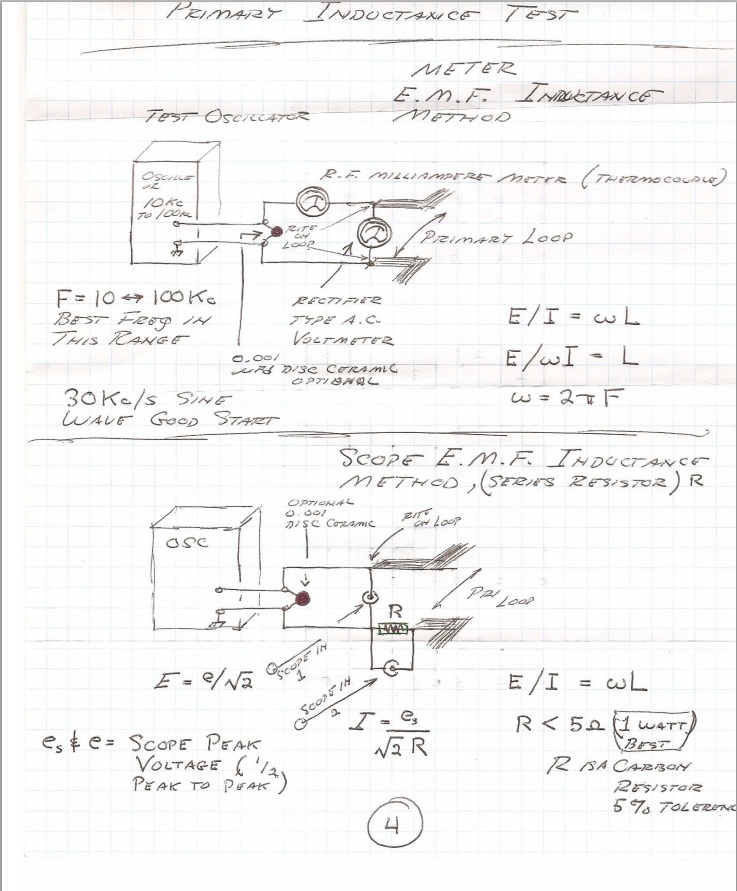
        In reviewing the Dr. Green material it can be seen that this extra coil is too large, or the wire is too long. Its resonant frequency, even with the lightest coupling, is far below that of the standardizing secondary frequency.

        Extra Coil Direct: 2695 Kc/sec
        Secondary, rings: 3670 Kc/sec
        Frequency ratio: 72% lower
        Wavelength ratio: 136% longer

        Here seen is that a smaller coil is needed.
        June 29 2012

        Originally posted by T-rex
        Extra Coil

        Dr Green;
        I believe that another extra coil needs to be made for a higher frequency, that of your secondary, 3670. So an extra coil for 3700 with some terminal loading. The extra coil that you have now is too large/long and many turns would have to be removed, best to keep this one intact. Since now you can see the actual extra coil relations from the one you made, now it can be scaled to any frequency. Break, more to follow...
        June 30 2012

        Originally posted by T-rex
        Dr Green Extra Coil

        3670 Luminal Wavelength
        81.70 Meters

        3670 Luminal Quarter Wave
        20.4 Meters

        Empirical Extra Coil Velocity Factor
        124%

        Extra Coil Wire Length
        16.5 Meters

        Wind your width equals height extra coil with 16.5 meters of 18 to 22 gauge transformer wire
        July 2 2012

        New extra coil:

        Diameter = 8.28cm
        Height = 8.28cm
        64.25 Turns
        Wire length = 16.47 metres 20 SWG (0.9mm)
        Luminal frequency = 4550.8 kc
        Free space frequency = 8509.996 kc

        New extra coil wire length = λ/4/1.24
        Where λ = c/F


        July 26 2012

        In trying to achieve a certain ratio between the Tandem mode and Concatenated mode frequencies, it has been found impossible to get the Tandem mode frequency above 1895 kc relative to 3670 kc;

        As the extra coil terminal capacitance is reduced, condenser rings capacitance increased, the Tandem mode frequency is brought up to a maximum of about 1895 kc.

        By continuing to reduce the terminal capacitance and increasing the rings capacitance, there comes a point that the Tandem mode frequency begins to go back down.

        This appears to be the case when the extra coil terminal capacitance is too small, and the rings capacitance too big to be practicable, the effect appearing to be accompanied by a reduced voltage measured through the pickup probe.

        This may be of particular interest when considering the fact that the old extra coil with 126 turns and 32.079 metres wire length Tandem mode frequency was 2340 kc, compared to the new extra coil of 64.25 turns and 16.47 metres wire length maximum measured Tandem frequency of 1895 kc; The Tandem frequency is LOWER with LESS "total" wire length:

        Resonant frequency ratio with old extra coil was around 1.56
        Resonant frequency ratios with new extra coil seems to be greater than 1.93

        In general the Tandem mode now appears to be acting as double the wire length at approximately half the frequency compared to the Concatenated mode.

        I'm also unable to get any more capacitance from the rings to be able to use even less extra coil terminal capacitance. The rings should be perfectly straight in order to get them as close as possible for purpose of this particular experiment, or bigger for more capacitance, but I don't think the coil is really usable in such a state. The 1895 kc maximum Tandem frequency seems to be the logical place to look first.
        Last edited by dR-Green; 10-20-2012, 04:08 AM.
        http://www.teslascientific.com/

        "Knowledge is cosmic. It does not evolve or unfold in man. Man unfolds to an awareness of it. He gradually discovers it." - Walter Russell

        "Once men died for Truth, but now Truth dies at the hands of men." - Manly P. Hall

        Comment


        • #5
          Very Nice!

          I have been busy with other things, magamp in particular and haven't gotten to wind my 1.9MHz CRI-based-TMT frames that a friend built for me. I will be definitely using this thread as a starting guide rather than searching thru the multiple fallen Dollard threads for the info.

          Thanks,

          Dave

          Comment


          • #6
            Originally posted by Web000x View Post
            Very Nice!

            I have been busy with other things, magamp in particular and haven't gotten to wind my 1.9MHz CRI-based-TMT frames that a friend built for me. I will be definitely using this thread as a starting guide rather than searching thru the multiple fallen Dollard threads for the info.

            Thanks,

            Dave
            Updated
            http://www.teslascientific.com/

            "Knowledge is cosmic. It does not evolve or unfold in man. Man unfolds to an awareness of it. He gradually discovers it." - Walter Russell

            "Once men died for Truth, but now Truth dies at the hands of men." - Manly P. Hall

            Comment


            • #7
              July 27 2012

              Today the coils were tuned with the intention of having the first and second resonant peaks in a ratio equal to 2. The Tandem mode frequency should therefore be 1835 kc.

              However the graphed results show a measured frequency of approximately 1832 kc, which is confirmed to be the resonant peak. This is possibly due to the condenser rings "settling down" after fine adjustment between the set up and the experiment, or movement in the extra coil terminal capacitance, which consists of a 330ml drink can with an additional 1.5 x 4 cm approx tinfoil leaf for fine adjustment.

              Rings capacitance = 43pF
              Extra coil terminal capacitance (to ground plane) = 7.6pF

              The measured ratio is therefore approx 2.00327. The test will most likely be carried out again.

              The secondary reading is not recorded in the 3670 kc peak test because there is hardly any reading to speak of. The "secondary" reading in the 1835 kc peak test is being picked up from the extra coil, not the secondary, therefore no magnification factor is given.


              Spectrum analysis:

              3670 kc Signal:

              First peak: 3670 kc
              Second peak: 7340 kc


              1835 kc Signal:

              First peak: 1835 kc
              Second peak: 3670 kc
              Third peak: 5505 kc
              Fourth peak: 7340 kc


              -----

              July 28 2012

              Free resonance test. The condenser rings arrangement has been removed, leaving one ring connected to the top end of the secondary. There is no extra coil terminal capacitance. The coil is set up as follows:


              Considering both coils as one length of wire,

              Secondary = 13.079 metres
              Extra coil = 16.47 metres

              Total = 29.549 metres

              Full wavelength = 118.196 metres

              Luminal frequency = 2536.401 kc

              Measured frequency = 3455 kc

              3455 / 2536.401 = 1.362...


              Spectrum analysis:


              The first and second peaks are seen to be in a ratio of 2, however taking the shown frequency of 9634 kc as an approximate value of the third peak,

              9634 / 3459 = 2.785...
              9634 / 6917 = 1.392...

              -----

              July 29 2012

              The extra coil was set up as in the July 27 experiment and tested separately for resonance. The coil is disconnected from the secondary but otherwise not moved, with the secondary short circuited.

              NOTE: The terminal can is not properly secured and has since been found to be an unreliable relation to the July 27 test. However, the two relative measurements that follow so far appear to be within reason for an approximation of the direct vs 10pF relations (to be confirmed at different frequencies). Terminal capacitance has been remeasured:

              Extra coil terminal capacitance (to ground plane) = 8.7pF

              Direct = 3253 kc
              10pF = 4070 kc


              In the 10pF spectrum analysis there can be seen some strange peak at around 7797 kc which goes away with different input signal frequencies.

              -----

              Extra coil is tuned to 3670 kc with direct connection to oscillator, ready for separate and concatenated testing tomorrow, with a (more reliable) terminal consisting of one big and one small connector clips attached to the 22mm copper tubing terminal support, moving one of which having the effect of varying the amount of exposed metal and therefore the capacitance. Initial opinion based on the 10pF input measured frequency is that the extra coil frequency might be a bit too low. Target for future test should be closer to 4550.8 kc with 10pF coupling.

              Terminal capacitance = 6.1pF

              Direct = 3670 kc
              10pF = 4378 kc


              10pF resonant at 4378 kc:


              -----

              July 30 2012

              The condenser rings have insufficient capacitance with the extra coil tuned to 3670 kc. The lowest obtainable frequency in the concatenated mode is 3892 kc. The top ring will need to be straightened along the horizontal axis, though I'm unsure whether the difference will be enough to bring the frequency down to 3670 kc. If not then the condenser plates will have to be used.

              Rings capacitance = 56.3pF

              First Peak Resonance: 3892 kc
              Second Peak Resonance: 1742.5 kc

              3892 kc Signal:


              Second harmonic: 7784 kc
              Third peak: 8324 kc ??

              1742.5 kc Signal:


              Second harmonic: 3485 kc
              Third harmonic: 5227.5 kc
              Fourth harmonic: 6970 kc
              Fifth harmonic: 8712.5 kc

              -----

              July 31 2012

              The condenser rings were straightened out as much as possible.

              Maximum rings capacitance = 63.65pF

              Lowest concatenated mode frequency = 3842 kc
              Tandem mode frequency = 1626 kc

              With this arrangement the output is not very strong.

              3842 kc = 36.9mV
              1626 kc = 73.5mV
              Last edited by dR-Green; 07-31-2012, 02:44 AM.
              http://www.teslascientific.com/

              "Knowledge is cosmic. It does not evolve or unfold in man. Man unfolds to an awareness of it. He gradually discovers it." - Walter Russell

              "Once men died for Truth, but now Truth dies at the hands of men." - Manly P. Hall

              Comment


              • #8
                Great Work

                Keep up the good work. Its sinking in. I found the answer to "why the connection between the extra/sec in this thread. Page three of the handwritten notes. Thanks for help.

                Would you please describe the the spectrum analyzer setup. I have been really intrested in what they would look like. And now I know. Thanks,

                Comment


                • #9
                  Originally posted by jake View Post
                  Keep up the good work. Its sinking in. I found the answer to "why the connection between the extra/sec in this thread. Page three of the handwritten notes. Thanks for help.

                  Would you please describe the the spectrum analyzer setup. I have been really intrested in what they would look like. And now I know. Thanks,

                  No problem

                  The spectrum analysis is just using the same pickups as for the voltage measurement. I'm using a USB oscilloscope (Pico ADC-200) using the meter display for each probe, with the probes across 430 ohm resistors with the 1N34 diode. So the software allows for multiple views, it's all coming from exactly the same source.
                  http://www.teslascientific.com/

                  "Knowledge is cosmic. It does not evolve or unfold in man. Man unfolds to an awareness of it. He gradually discovers it." - Walter Russell

                  "Once men died for Truth, but now Truth dies at the hands of men." - Manly P. Hall

                  Comment


                  • #10
                    I am really impressed by the workmanship displayed here.
                    (and regret to say it looks better than mine...)
                    I am also a bit puzzled as to why on some points the Colorado Spring Notes are followed and on some other points deviated from.

                    Anyway, we now have a new unit for field intensity: μA/beercan

                    Keep up the good work!

                    Comment


                    • #11
                      Thanks Ernst Although all the maths and what not is Eric's work. The coil calculations were experimental, now some of us have built and tested it, the results have been applied to the Colorado Springs setup, and now thanks to Eric it can be scaled to any size. The idea here is also to turn a TMT into a crystal radio receiver to receive the Telluric signal from a local radio station. I'm just working on finding out what I can with a small coil before I build a bigger one for this purpose.

                      This is all in the EPD threads but I started this one to keep all the coil data in one place. Eric enters the discussion on page 3 here then later is (was) posting as T-rex.

                      http://www.teslascientific.com/

                      "Knowledge is cosmic. It does not evolve or unfold in man. Man unfolds to an awareness of it. He gradually discovers it." - Walter Russell

                      "Once men died for Truth, but now Truth dies at the hands of men." - Manly P. Hall

                      Comment


                      • #12
                        July 31 2012

                        The condenser plates are now used.

                        Extra coil direct = 3670 kc
                        10pF = 4378 kc
                        Terminal capacitance = 6.1pF

                        Secondary with plates = 1070 kc
                        Plates capacitance = 169.2pF

                        First peak resonance: 3670 kc
                        Second peak resonance: 1051 kc

                        3670 = 10.5mV
                        1051 kc = 51.3mV (extra coil), 61mV (secondary)

                        Spectrum:


                        Tested separately, the secondary is resonant at 1070 kc:


                        Conclusion: An extra coil frequency of 3670 kc with direct connection is too high. Perhaps around 3670 kc with 10pF input...

                        -----

                        August 6 2012

                        Tentative tuning relations are now established.

                        Voltage and capacitance readings are not accurate and are for general reference only. All measured frequencies should be within around +/- 5 kc tolerance (namely the extra coil direct measurements with bigger terminal capacitance are most difficult to pinpoint) (at the general system frequency of 3670 kc). Percentages are relative to system F therefore the relations are theoretically scalable. This must be verified.


                        -----

                        August 7 2012

                        The same data but with the graph based around the tuning of the secondary. Chart Three includes the measured extra coil frequency percentage relative to the luminal frequency of the extra coil with a wire length of λ/4/1.24


                        -----

                        August 12 2012

                        Test to determine the approximate magnification factor of Extra Coil at different frequencies through use of various terminal capacities; as coil was used in previous test.

                        The Extra Coil is left in place and the secondary is disconnected from earth and short circuited. Using the normal Extra Coil testing method with direct connection and 10pF.

                        The data is integrated into the previous test results. The Magnification Factor (n) is a numeric value, not a percentage (for example, 20% on the vertical axis = Magnification Factor 20). Results are as follows:


                        -----

                        August 13 2012

                        Test to determine secondary coil magnification factor at different frequencies.

                        The secondary coil is tested alone. The test begins with the secondary tuned to 47% of F as that is the lowest frequency possible with the condenser rings and any lower would require the use of the condenser plates. It has already been established that the coil is not optimised when tuned to such low frequencies therefore those frequencies are not tested here.

                        The data is again integrated into the previous test results. The vertical axis represents the magnification factor as a numeric value, the horizontal axis represents the secondary tuning relative to F. The voltage reading follows the same arrangement. 40% vertical axis = 40mV.


                        -----

                        August 14 2012

                        A general idea of the secondary coil Magnification Factor is now established. As tested alone:

                        Free Maximum Frequency = 4126 kc
                        Magnification Factor = 63.70233

                        Condenser Rings = 3670 kc
                        Magnification Factor = 83.71159

                        Peak Magnification Factor Frequency = 2230 kc
                        Magnification Factor = 128.8150289

                        -----

                        August 15 2012

                        The existing extra coil frame was rewound with a wire length of 25.32 metres of 24 SWG for testing, with focus to be on frequency and magnification factor. Wire length = λ/4*1.24, or F/1.24.

                        -----

                        August 20 2012

                        New Extra Coil #2:

                        Wire length = λ/4*1.24

                        97.25 Turns
                        Diameter = 8.28cm
                        Height = 8.28cm
                        Conductor length = 25.323 metres 24 SWG

                        Luminal Frequency = 2959.677 kc
                        Direct = 3522 kc - Magnification Factor = 47.59459459
                        10pF = 3831 kc - 60.39728835

                        Direct:Luminal = 118.9%
                        10pF:Luminal = 129.4%


                        -----

                        Test to determine the magnification factor of the extra coil at different frequencies through use of terminal capacities.

                        Results are not 100% accurate but should be good enough for a general idea. The peak magnification factor will be more closely inspected at a later date.


                        Last edited by dR-Green; 08-20-2012, 09:57 AM.
                        http://www.teslascientific.com/

                        "Knowledge is cosmic. It does not evolve or unfold in man. Man unfolds to an awareness of it. He gradually discovers it." - Walter Russell

                        "Once men died for Truth, but now Truth dies at the hands of men." - Manly P. Hall

                        Comment


                        • #13
                          Don't forget the primary

                          Placing the large flat primary on the setup drops the frequency. Increasing the capacitance on the primary decreases frequency.

                          With the large primary I can get the same output from pri/sec combo at night(1000watts), than I can during the day(10,000watts) with the test coil.

                          Love your continious work. I can't wait until the kids go back to school. I had a blast with them but summers almost over.

                          Comment


                          • #14
                            Thanks Jake Yes good point about the primary and condenser. I haven't even started looking there yet. The focus has been the secondary to extra coil relations, I've just finished a lot of testing to that end. The hope is that the secondary frequency is what it is, whether the primary condenser is there or not. As long as the frequency is right then the primary can be tuned to that. Or at least that's the idea at the moment. [edit] The primary and secondary as a whole that is, relative to the extra coil frequency. I'm not too concerned with what the rings capacitance actually is because that will definitely be different on each setup so that's just for reference, plus the tuning is so sensitive I can't even connect the capacitance meter without moving the rings slightly so it can't be 100% accurate.

                            What do you mean by the 1kW and 10kW?

                            Bummer for the kids, worst time of the year for sure hehe
                            Last edited by dR-Green; 08-06-2012, 11:58 AM.
                            http://www.teslascientific.com/

                            "Knowledge is cosmic. It does not evolve or unfold in man. Man unfolds to an awareness of it. He gradually discovers it." - Walter Russell

                            "Once men died for Truth, but now Truth dies at the hands of men." - Manly P. Hall

                            Comment


                            • #15
                              August 20 2012

                              Test to determine the resonance of the concatenated coils when they are free; no additional capacitance.

                              The new extra coil #2 is connected to the secondary for the first time. The condenser rings are removed but the ring on the top of the secondary left in place. The secondary probe is approx 25cm away on the same horizontal axis as the ring on the top of the secondary. The extra coil probe is approx 46cm above the extra coil.

                              Two resonant peaks are found.

                              F = 3670 kc

                              Peak #1 = 3023 kc
                              Ratio = 82.37%

                              Peak #2 = 4515 kc
                              Ratio = 123%


                              -----

                              August 22 2012

                              Tentative tuning relations for the "new extra coil #2" with a conductor length of λ/4*1.24 are now established. The extra coil frequency measurements with the given terminals are taken from the August 20 tests.


                              -----

                              September 5 2012

                              This test involves shorting the extra coil to measure the resulting frequency.

                              The measured output difference between secondary and extra coil pickups is in accordance with tandem mode measurements.

                              This data is taken from previous tests, the same setup is being used for this test.

                              Extra Coil Terminal = Terminal Block
                              F = 3670 kc
                              Tandem = 2180.7 kc
                              Secondary = 2370.8 kc
                              Extra Coil Direct = 3489.7 kc
                              Extra Coil 10pF = 3805.1 kc

                              Concatenated Mode output (pickup):
                              Secondary = 10mV
                              Extra Coil = 55.9mV

                              Tandem Mode output (pickup):
                              Secondary = 67.6mV
                              Extra Coil = 179.4mV

                              -----

                              Test 1:

                              Coil is tuned approximately as above, there is a slight deviation.

                              F = 3670 kc
                              Tandem = 2175 kc

                              The Extra Coil is shorted with approx 18cm length of wire. Only one resonant peak found.

                              Frequency = 2248 kc

                              Output (pickup):
                              Secondary = 66mV
                              Extra Coil = 163mV

                              -----

                              Test 2:

                              The same piece of wire is used this time as a vertical terminal capacitance.

                              Extra Coil Terminal = 18cm vertical wire
                              F = 3670 kc
                              Tandem = 2388 kc

                              Secondary frequency with extra coil disconnected, in place and free = 2917 kc
                              Secondary frequency with extra coil disconnected, in place and shorted = 2935 kc

                              Concatenated Mode output (pickup):
                              Secondary = 4.6mV
                              Extra Coil = 55mV

                              Tandem Mode output (pickup):
                              Secondary = 79mV
                              Extra Coil = 167mV

                              The wire used as terminal capacitance is used to short the extra coil.

                              Frequency = 2686 kc

                              Output (pickup):
                              Secondary = 79mV
                              Extra Coil = 187mV

                              -----

                              September 28 2012

                              Updated tuning data with Magnification Factor.

                              Pickup Distance:
                              Secondary = 22cm
                              Extra Coil = 28cm

                              Sec = Secondary
                              ECD = Extra Coil Direct
                              EC10pF = Extra Coil 10pF
                              C-EC-MF = Concatenated Mode Magnification Factor (Extra Coil Pickup)
                              T-EC-MF = Tandem Mode Magnification Factor (Extra Coil Pickup)


                              -----

                              September 28 2012

                              3670 kc Luminal Wavelength
                              81.687 Metres

                              3670 kc Luminal Quarter Wave
                              20.421 Metres

                              Empirical Extra Coil Velocity Factor (Direct Connection)
                              119%

                              Extra Coil Wire Length
                              24.308 Metres

                              -----

                              New extra coil #3:

                              Diameter = 8.28cm
                              Height = 8.28cm
                              93.25 Turns
                              Wire length = 24.256 Metres
                              Luminal frequency = 3089.819 kc
                              Free space frequency = 5777.961 kc

                              Measured Frequency:
                              Direct = 3676.7 kc
                              10pF = 3990.5 kc

                              Direct:luminal = 118.99%
                              10pF:luminal = 129.14%

                              Taking the ratio of the free space to actual measured velocity gives
                              1.5715 numeric (close to Pi/2)


                              Measurements:

                              2.5pF = 4030 kc
                              5pF = 3964 kc
                              10pF = 3887 kc
                              25pF = 3786 kc
                              50pF = 3737.5 kc

                              Spectrum Analysis:

                              Direct:


                              Harmonics:

                              332.2 kc
                              1602 kc
                              3676.7 kc (Fundamental)
                              5276 kc
                              7367 kc
                              8969 kc

                              10pF:


                              Harmonics:

                              3990.5 kc (Fundamental)
                              6019 kc
                              7992 kc

                              Notes:

                              The 10pF frequency in the frequency vs capacitance test is lower due to a longer input wire being used, as the different capacitors can't be suspended in mid-air, so the same length of input wire is used for all capacitance tests for relative consistency for the particular test.

                              Capacitors used for frequency vs capacitance test:

                              2.5pF = 4x series 10pF ceramic
                              5pF = 2x series 10pF ceramic
                              10pF = Ceramic
                              25pF = Vacuum (10kV)
                              50pF = Vacuum (15kV)

                              -----

                              October 2 2012October 3 2012

                              Secondary Coil Review

                              Free:Tuned:October 17 2012

                              Test with New Extra Coil #3, Concatenated Resonance:

                              Extra coil has no terminal capacitance. Secondary is tuned via condenser plates for maximum (Concatenated) potential at 3670 kc. Output = approx 12mV.

                              Frequency sweep reveals that the actual peak is approx 3695 kc, output = approx 18mV.

                              Impossible to achieve this same output with any tuning of the condenser plates for the intended frequency of 3670 kc.
                              Last edited by dR-Green; 10-20-2012, 04:17 AM.
                              http://www.teslascientific.com/

                              "Knowledge is cosmic. It does not evolve or unfold in man. Man unfolds to an awareness of it. He gradually discovers it." - Walter Russell

                              "Once men died for Truth, but now Truth dies at the hands of men." - Manly P. Hall

                              Comment

                              Working...
                              X