This forum is preserved as a permanent archive. The community continues at eMedia Press.

Announcement

Collapse
No announcement yet.

Eric Dollard�s Cosmic Ray Detector

Collapse
X
 
  • Filter
  • Time
  • Show
Clear All
new posts

  • Eric Dollard�s Cosmic Ray Detector


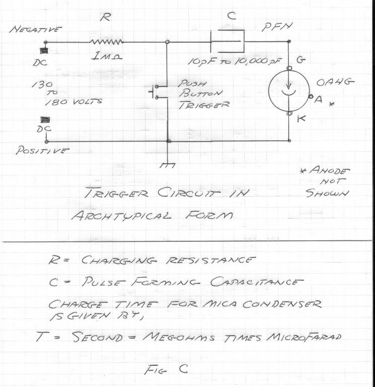
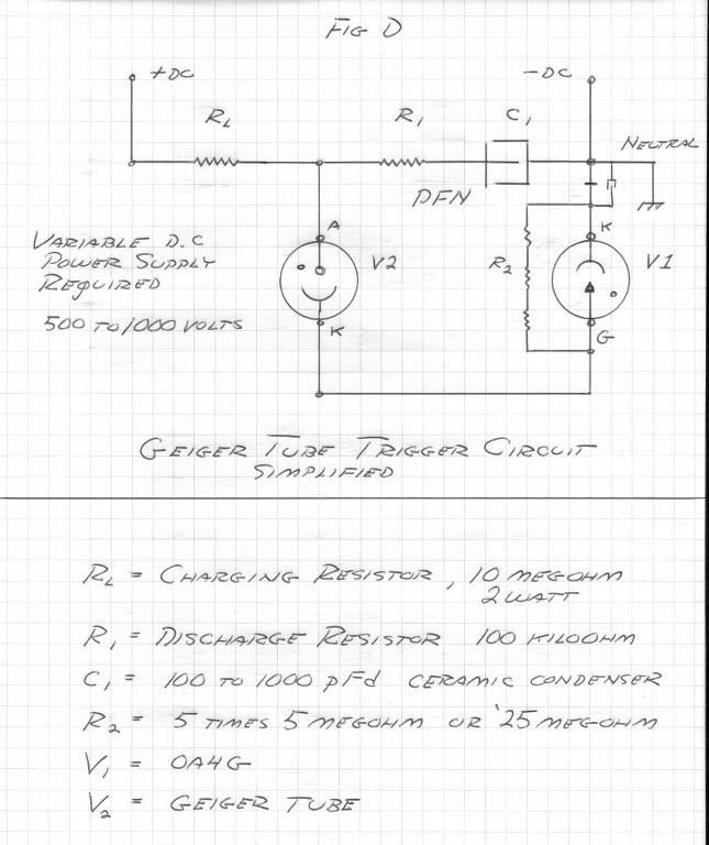
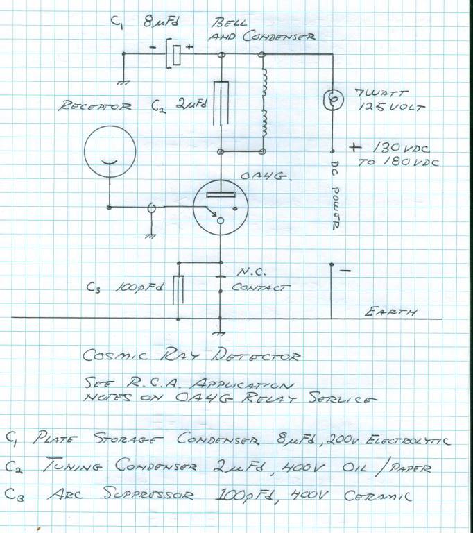
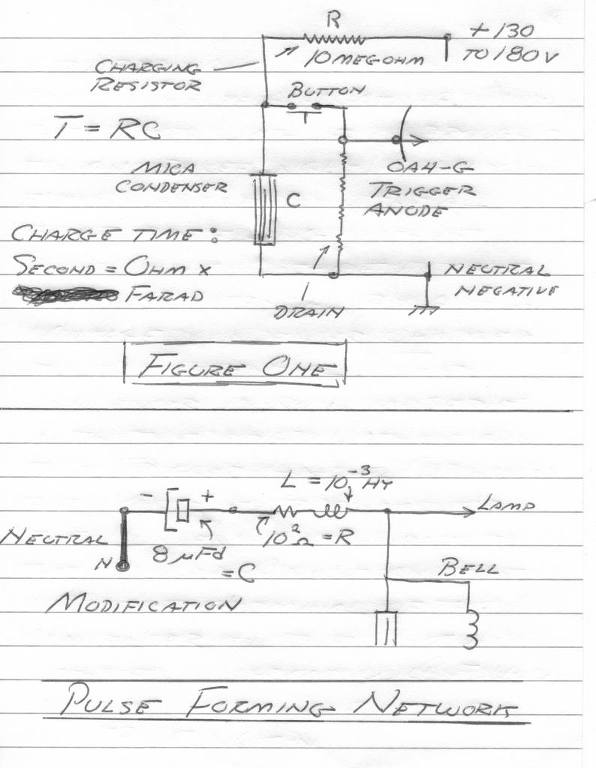
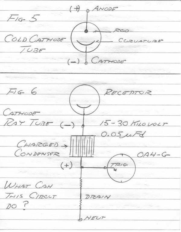
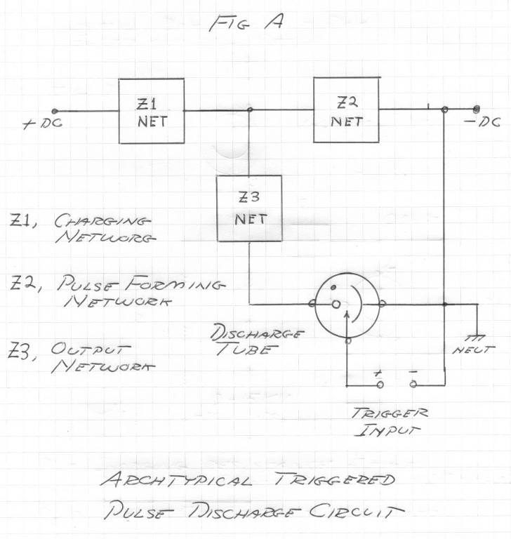
    The OA4G has application as a radiant matter detector. The main circuit consists of a Western Electric Telephone Bell in series with the plate supply. The bell condenser should be connected in shunt to the bell windings. A contact should be fitted to the bell armature to break the cathode connection to the OA4G in order to reset the tube. See the Marconi Coherer detector.

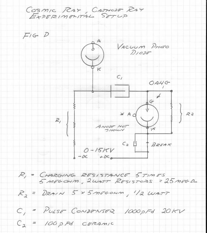
    (4) The cosmic anode lead connects to the trigger or grid lead of the OA4G. There must be NO DC leakage to ground. For cosmic anodes see Vassilatos "Vril Compendium", and the experiments of Luigi Galvani.

    (5) As for detectors into the outer limits the common regenerative detector is the circuit of choice. It is a development of E.H. Armstrong, see "Empire of the Air". The Regenerative Detector is also developed in the Russian parametric paper, an important study. Radionic receivers here are possible, depending on the metallic-dielectric geometry used. Connection with a magnification transformer is possible.

    Updated Circuit:


    A capacitor has been added to charge the cathode to a negative high potential. This facilitates the tube being able to emit. The capacitor will be in one of two states, either charging (out of the circuit), or running (connected to the cathode)
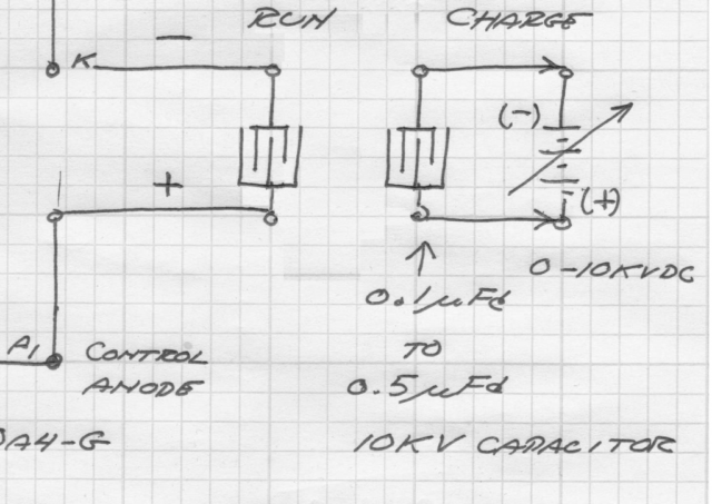


    The HV DC charging source must not be in the tube circuit. The smallest possible capacitance that still allows the tube to fire is desirable. A small capacitance won't have enough stored energy at low voltages however, so high voltage DC is required: 0-10 KV.

    Different capacitor values at different voltages need to be tried, experimentation is required. Curves need to be drawn showing the minimum voltage at a given capacitance is required.
    The HV DC charging source must not be in the tube circuit. The smallest possible capacitance that still allows the tube to fire is desirable. A small capacitance won't have enough stored energy at low voltages however, so high voltage DC is required: 0-10 KV.

    Different capacitor values at different voltages need to be tried, experimentation is required. Curves need to be drawn showing the minimum voltage at a given capacitance is required.
    "Doesn't matter how many times you kick the coyote in the head, it's still gonna eat chickens". - EPD

  • #2


    "Doesn't matter how many times you kick the coyote in the head, it's still gonna eat chickens". - EPD

    Comment


    • #3


      "Doesn't matter how many times you kick the coyote in the head, it's still gonna eat chickens". - EPD

      Comment


      • #4
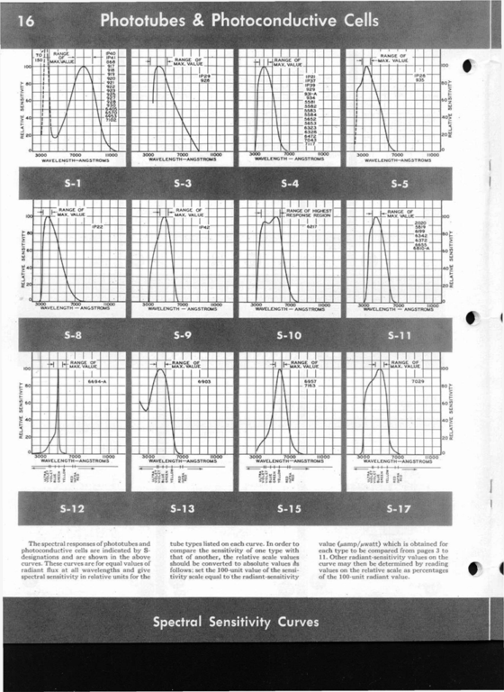
        Phototubes

        Spectral Curves


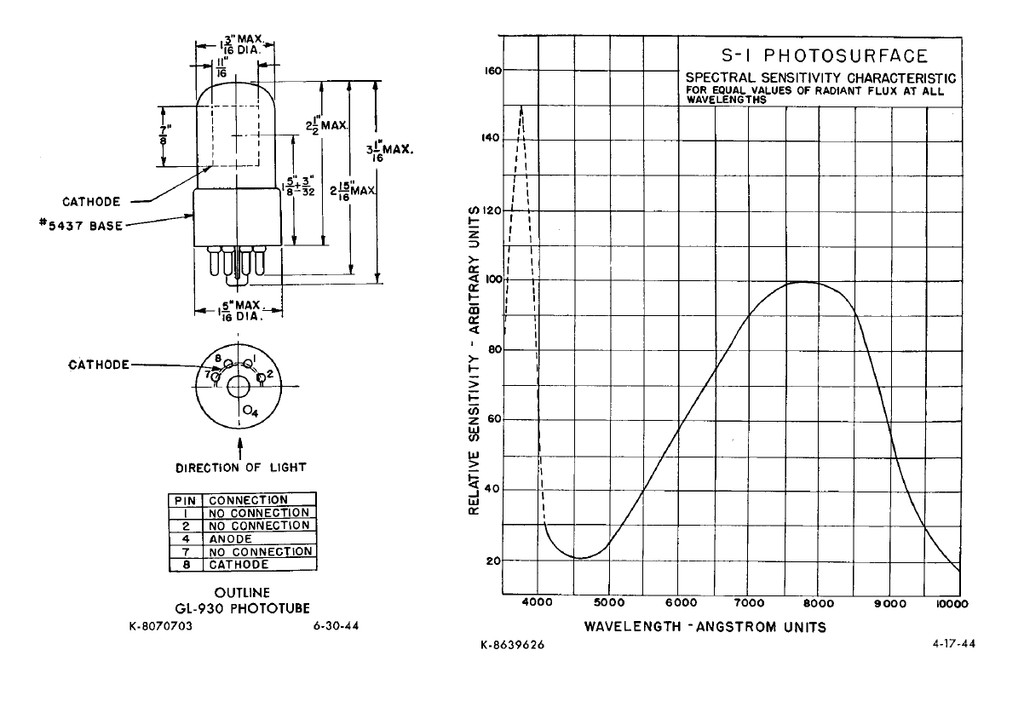
        Spectral Curve 930 Phototube (1P40)


        RCA Phototubes:

        http://www.tubebooks.org/Books/Atwoo...Phototubes.pdf
        "Doesn't matter how many times you kick the coyote in the head, it's still gonna eat chickens". - EPD

        Comment


        • #5

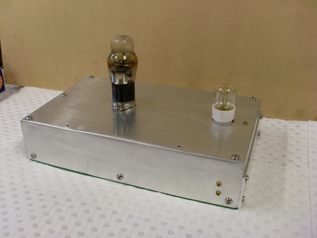
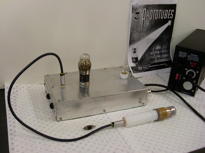
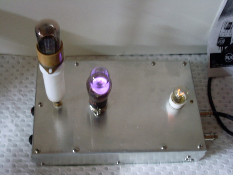
          Cosmic Ray Detector housing


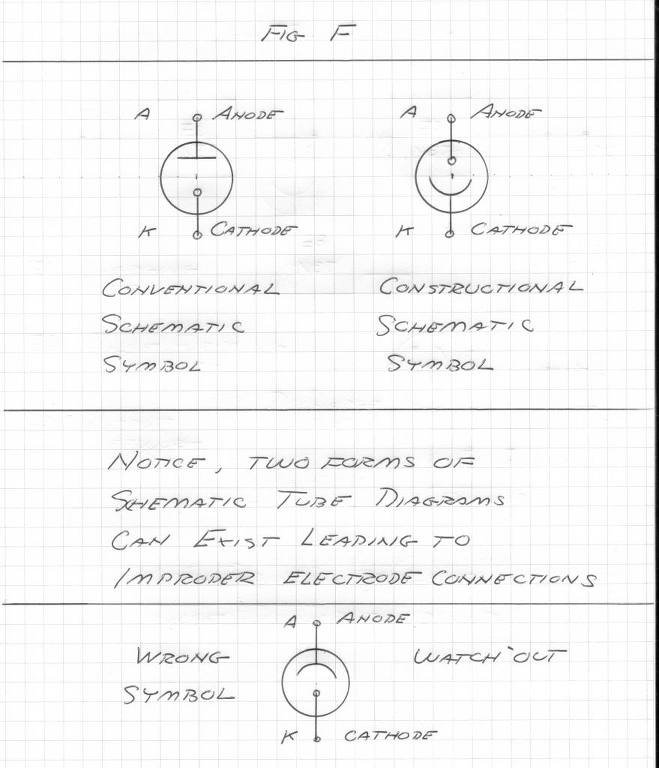
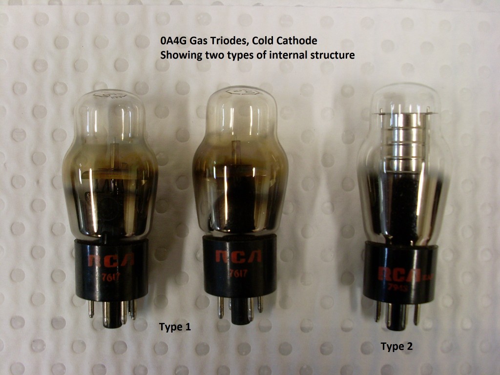
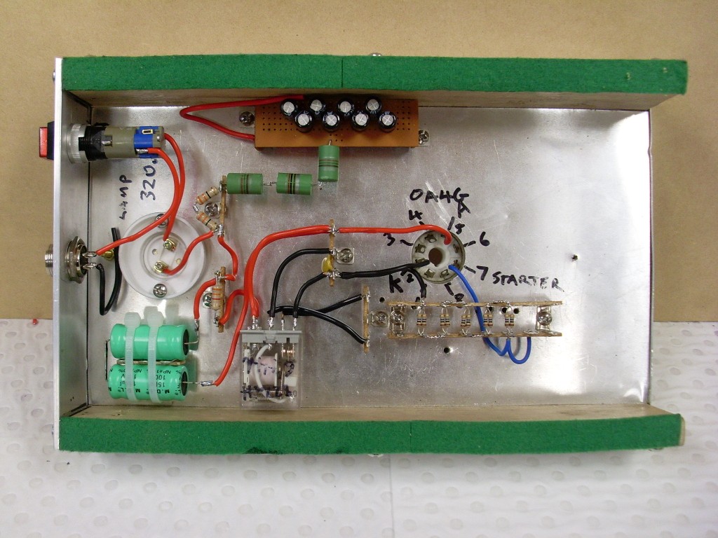
          04AG Gas Triode, Cold Cathode, Starter Anode Type.
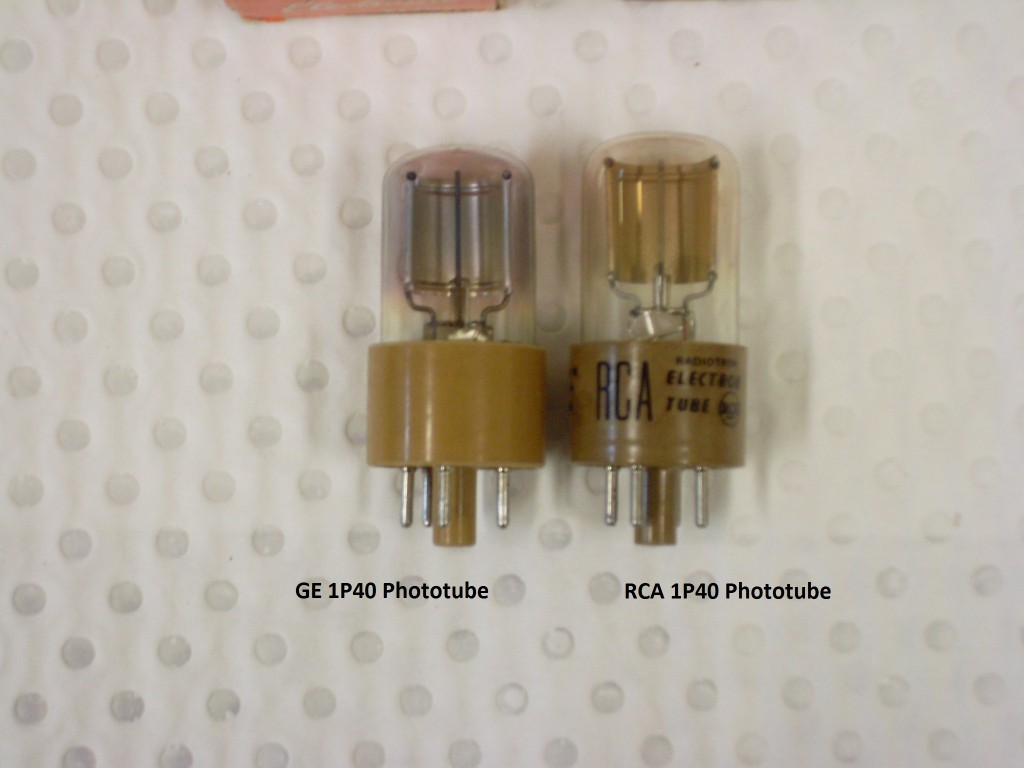
          1P40 Phototubes, one is a RCA branded one, the other a General Electric version.The Vintage Technology Association - Detection Tubes
          Last edited by Sputins; 08-22-2014, 03:38 AM.
          "Doesn't matter how many times you kick the coyote in the head, it's still gonna eat chickens". - EPD

          Comment


          • #6


            Sputins
            "Doesn't matter how many times you kick the coyote in the head, it's still gonna eat chickens". - EPD

            Comment


            • #7
              CRD Construction, part 2.

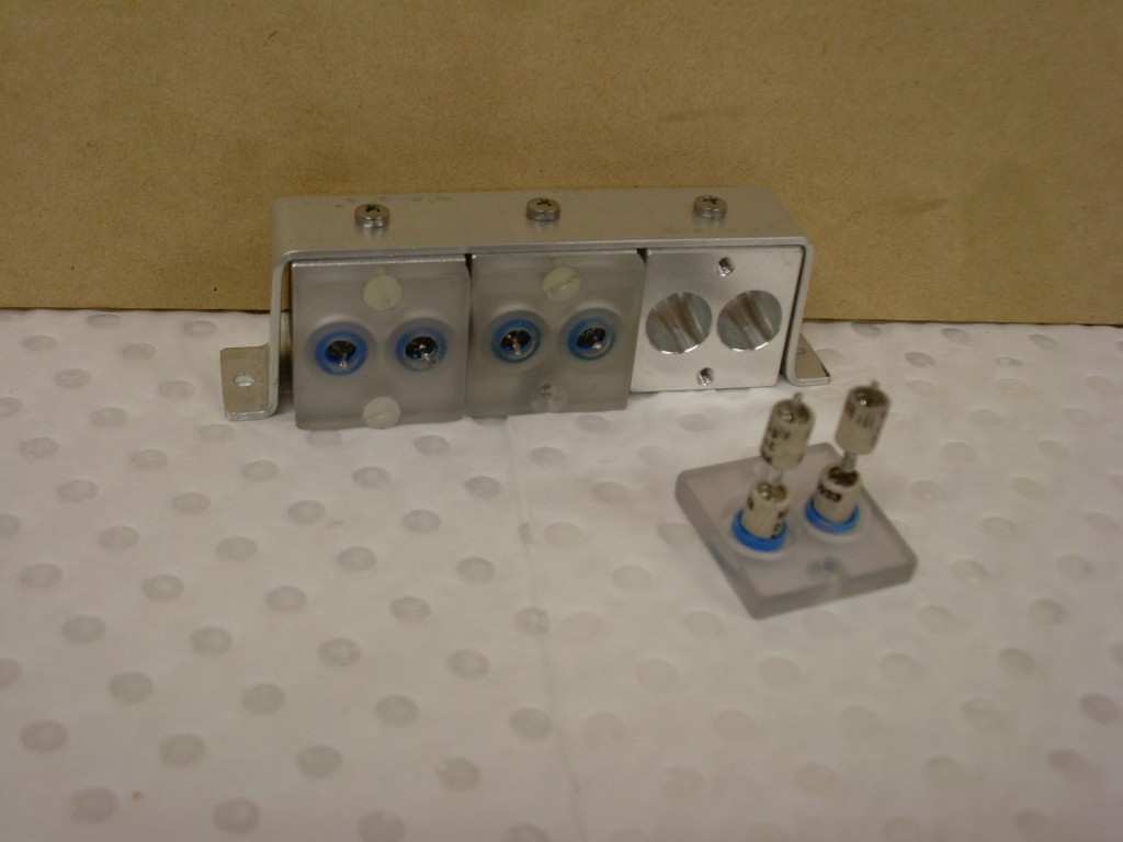
              HV capacitors:

              These are tiny HV capacitors, two times [series] 2pF @ 5KV, to give 1pF @ 10KV. Six in parallel gives 6pF at 10KV. This is for the HV cap to assist the cathode of the 1P40 Phototube as per the circuit. Capacitors come with their own aluminium housing [shield]. (Extracted from old ICPMS instruments). Other caps to try if unsuitable or if capacity is too low.


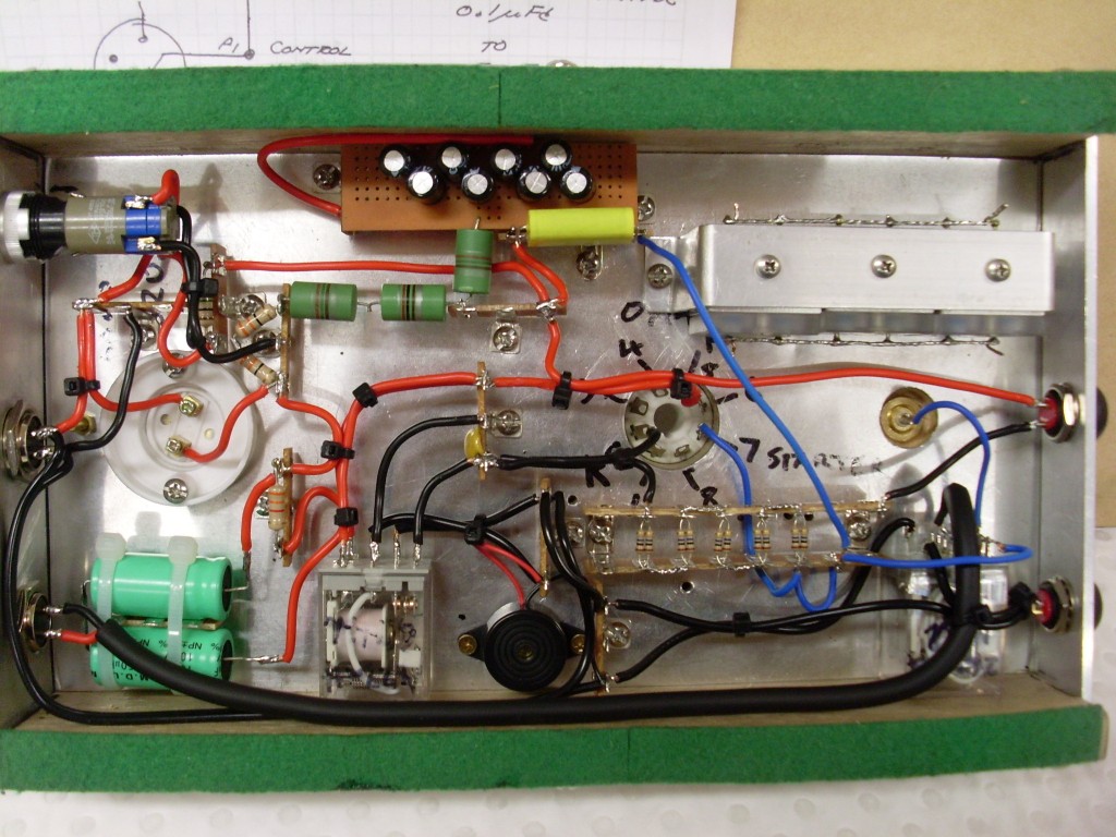
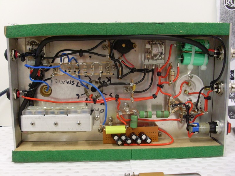
              Underside part2:

              Circuit is based on both the 0A4G test fire circuit together with the updated Phototube detection circuit the Cosmic Ray Detector. (Both circuits in one)


              There are inputs for up to 190V DC, 12VDC (relay coil and buzzer) and HV cap charging supply 0-10KV.

              The test fire circuit is complete, with testing to begin very soon.

              HV supply, Phototube detector housing and various arrangements to follow in part 3.

              Sputins.
              Last edited by Sputins; 09-26-2014, 01:18 AM.
              "Doesn't matter how many times you kick the coyote in the head, it's still gonna eat chickens". - EPD

              Comment


              • #8


                "Doesn't matter how many times you kick the coyote in the head, it's still gonna eat chickens". - EPD

                Comment


                • #9
                  Cosmic Ray Detector

                  I assume that the Cosmic Ray Detector is built so when someone builds the Cosmic Ray collector they can use the detector to make sure it is built right and really collecting Cosmic Ray?

                  I can not think of another reason for having one.

                  Where is the collector thread?

                  Mikey

                  Comment

                  Working...
                  X