

 Tweet
Tweet
That looks like Telflon Plumbing tapepolytetrafluoroethylene
-
"Amy Pond, there is something you need to understand, and someday your life may depend on it: I am definitely a madman with a box." ~The Doctor -
Hi Everyone,
Today I wanted to analyze the Nichrome Power / Temperature curves to see what wire size really gives the best thermal profile against the power required to produce that temperature. We already knew that the smaller wire was able to produce vastly hotter outputs for much less current, but because the resistance of the wire goes up with the smaller gauge wire, it demands more voltage to push the current through that higher resistance.
But the question was, how much voltage, or more importantly, how much power?
Fortunately, we do have a table for the temperature for N series resistance wire:
Nichrome N8 Amperage / Temperature TableClick Here For Larger ImageLast edited by Harvey; 04-08-2010, 02:23 AM."Amy Pond, there is something you need to understand, and someday your life may depend on it: I am definitely a madman with a box." ~The DoctorComment
-
Heater
Hi Harvey interesting that you've posted regarding the gauge. Did anyone try modifications on the circuit for a bigger resistance heater?
ThanksComment
-
Last edited by Harvey; 04-09-2010, 08:56 PM."Amy Pond, there is something you need to understand, and someday your life may depend on it: I am definitely a madman with a box." ~The DoctorComment
-
-
Guys thanks so much for all this, all is in your PDF and will be up ASAP Finished our rep to send in for a good scope just about to send Harvey and Glen the snaps of the device, hope to get some measurements and publish back up results to support Harvey and Glen.
AshComment
-
Comment
-
Here are some early posts I made discussing the 555 timer circuit -
This post to Aaron was discussing the original Quantum (Buckley) Circuit:
Here was my first post regarding the proposed changes to prevent the overheating:
This Post contain a link to the previous post:
This is Aaron's acknowledgment of the proposed changes:
This post was a reminder that a solution to reducing that heating was provided earlier:
It really isn't a big deal - but its a simple modification that removes one component, gives better adjustment and stops the discharge heating.
Cheers!
 "Amy Pond, there is something you need to understand, and someday your life may depend on it: I am definitely a madman with a box." ~The Doctor
Comment
-
555 info and other tips
Harvey,
Thanks for this extra information. I guess this should be enough variations and info now to have my setup 'oscillating'. I will give it another try during the weekend.
I got a list of tips from Glen as well and something from Rosemary. If I shake all this together it simply has to work.
If it still doesn't work I will eat my shoes ...
Cheers,
BComment
-
Hi Bart,Originally posted by b4FreeEnergy View Post
I was going over some of the old stuff and ran across these two videos from August of 2009 - you may find something useful in there for getting the 555 to retrigger:
YouTube - RA Gate Oscillations Part One
YouTube - RA Gate Oscillations Part Two
Cheers!
"Amy Pond, there is something you need to understand, and someday your life may depend on it: I am definitely a madman with a box." ~The DoctorComment
-
Hi,
I am looking for a 555 Circuit too right now. Something, what can increase frequency, but stay stable with the Duty cycle.
A online Lession showed a simple Principle from the Timer.
LM555. Scroll down a bit for the Block Diagram.
When V-source is ie. 8 Volt, the Voltage is internal divided with the 3 Resistor to 6-4-2 Volts.
Comparator 1 + 2 are at the pickup from 6 and 4 Volt from the Capacitor,
Pin 6 (Comp1) turns at 6 Volt Pin3 (Output) to high,
Pin 2 (comp2) at 4 Volt Pin3 to low.
BUT! the NE555 timer has an inverted Amplifier at the output,
what makes the (greater as)>2/3 Vcc at Pin6 to low on Pin3 (Output), but high before the Inverter,
that discharge the Cap over Pin7, when triggering the Base of the Transistor (Pin7)
Inputs of 555/556
The Cap discarge over Pin7 and the Resistor(2) until ~3V, then, Pin2 close the Transistor at <1/3 Vcc and Pin7 with low Output,
but the Inverter turns the Output (Pin3) High, and the cycle starts again.
The upper Resistor is there to dont make a short at the Discharge.
Here you see again the Transistor at Pin7,
and that what he labeled as Output Stage is the Inverter.
Its an inverting Amplifier, and i dont know, if the LM555 has it, but the NE555 do.
In this timer Circuit what is used, the Cap is better buffered and adjustable, more or less good.Theorizer are like High Voltage. A lot hot Air with no Power behind but they are the dead of applied Work and Ideas.Comment
-
Hi Joit,
They are the same, so the inversion is in place for them all, but I did find some schematics with errors regarding this - but in practice, they do work the same.
However, some are much faster, like the TLC version and some are lower power. So they have other properties that make them function different for certain applications - but the timing structure is always the same based on thirds. So they are very stable timing over a wide range of voltages - this is the most attractive feature of the 555 design.
To get a stable duty cycle with variant frequency only requires one thing - a variable capacitor. Use your charge, discharge resistors to set the duty cycle and vary the cap for frequency.
You will note that many engineers have added the diodes to give better control by splitting the charge and discharge sections. This is because typical applications use the same resistor to charge and discharge through and this is added in series with another on the charging which hampers easy adjustment of the duty cycle. So adding the diodes solves that problem allowing each side to function independently.
You may notice that the 'Proposed Changes' schematic that I provided, keeps the discharge clamp - this ensures that the device truly completes the discharge cycle prior to recharging. However, it should be carefully observed that too little resistance on the charge circuit can allow the discharge transistor to drop the supply voltage and cause a reset condition. (something Aaron designed purposely by adding resistance to his negative dominant circuit supply line).
The 555 is a very versatile chip with many variants - but a good understanding of how it works is critical in getting the desired results.
"Amy Pond, there is something you need to understand, and someday your life may depend on it: I am definitely a madman with a box." ~The DoctorComment
-
Thanks Harvey,
that the nect on my to-buy List, variable Capacitors Theorizer are like High Voltage. A lot hot Air with no Power behind but they are the dead of applied Work and Ideas.
Comment
-
Back to Basics
After wasting most of the day yesterday dealing with timing errors in my Spice simulator and getting no where I decided to take a break from it today and catch up on some reading etc.
I see that there are still some experimenting with the RA circuit and the questions regarding energy gains persist. The test of choice used to demonstrate energy gains was Test #13 (data here) [thanks to Rapid Share we have lost our Forum images for display] but I have uploaded the table of interest to my forum gallery for linking:
 Click Here For Full Imageresistor DC baseline
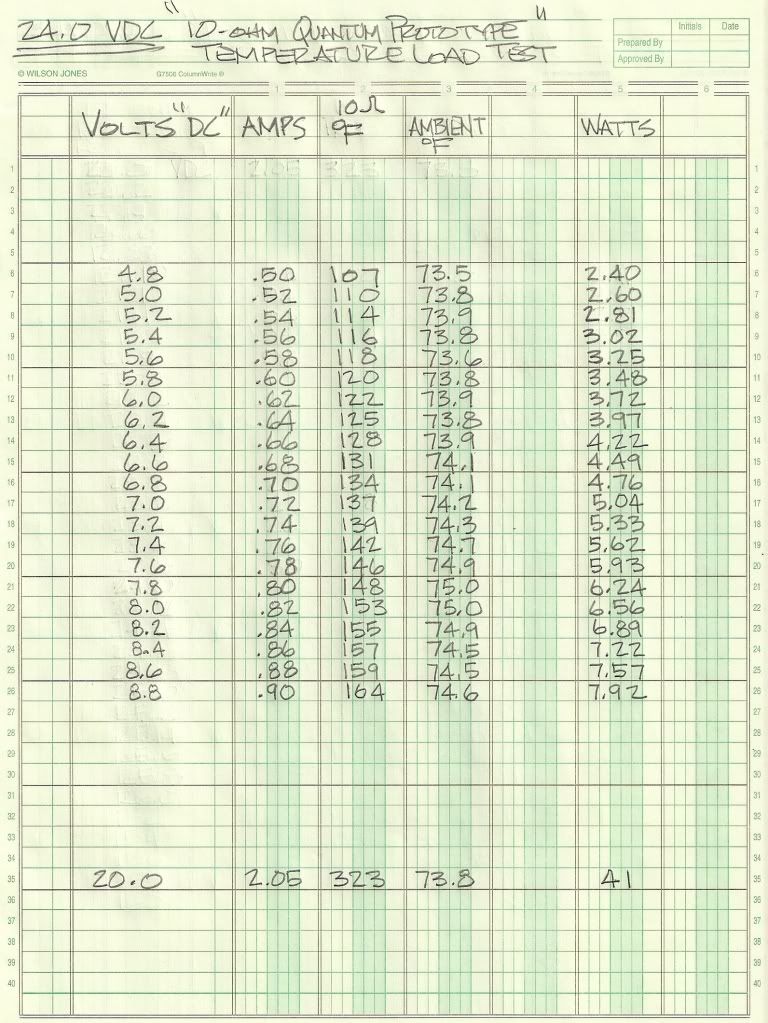
we see this corresponds to ~7.1V @ 0.73A or 5.183W on average. Notice that the voltage divided by the amperage is less than 10 ohms at that temperature and is really about 9.73 Ohms.
Looking at the gate pulses of Test 13, we find that the circuit adopts a duty cycle of about 50%, but what is it really? Let's look at the data:
 Click Here For Larger Image
So we see the on period of our MOSFET is really a bit more, 57.32%.
Now for how this all ties together:23.90W aperiodic operation.
That is just a basic analysis - how could it be that we are getting such a low heat if we are consuming such great power? Something isn't right. Clearly, a DC analysis simply fails to give the correct answer.
Remember the leap of faith? Did that set off any RED ALARMS? It should, because that is where the analysis breaks down. The resistor is more than a resistor, it is also an inductor and it has impedance relative to the frequency of operation. So it's true resistance to current flow is greater, and our current will be less accordingly.
Here are some questions to answer regarding Test #13:
What is the frequency?
What is the impedance of the load resistor?
What is the real power being dissipated?
How does a square wave affect the impedance of an inductor?
If the resistor was non-inductive, would the frequency make any difference as long as the duty cycle remained constant?
A DC treatment of the data obtained led us to believe that we were only using 1.3W and that the power dissipated was equivalent to that of 5.18W - does this seem reasonable? That is a gain of 398%. Clearly we need to identify how we get from 23.90W to 1.3W and we need to understand how we keep the heat. Clue: Perhaps there is AC power in the system
"Amy Pond, there is something you need to understand, and someday your life may depend on it: I am definitely a madman with a box." ~The DoctorComment
-
Comment
Comment