Good read, thanks
Announcement
Collapse
No announcement yet.
Use for the Tesla Switch
Collapse
X
-
-
A BETTER DESCRIPTION OF THE DIODE PLUG CIRCUIT
Comment
-
I did a TS-motor today, 4 batteries and 6 SS-relays.
Very simple, didn't perform well.
The relays are rather slow, I know, but easy to work with.
I was just about to make a video when I burnt something.
I had replaced 3 of the batteries with caps and used the replaced batteries in series with the remaining battery to inc voltage.
The circuit didn't like the fifth battery.
I don't like the TS.
At all.
I had just figured out the basics of a transistor-version that I thought I'd try.
I'm not so sure I'll do that anymore.
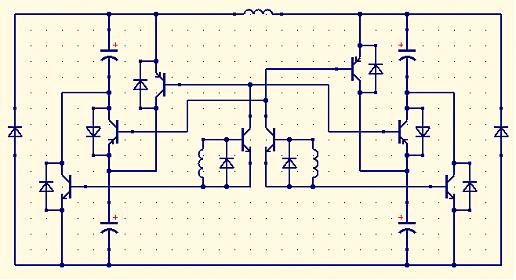
But I've posted the circuit below if anyone would like to comment.
The "sequental bipolar circuit" or similar is a better choice I think.
Nothing magical about the TS that can't be done in simpler ways is seems.
I think I'll abandon the TS-ship now.
Arrrggggh!
Hob Nilre
http://www.youtube.com/nilrehob
Comment
-
You gotta have some pretty big transistors, to drive it that way.
If your not switching fast enough it is not very impresive, but as the rate of switching gets higher it starts to act different. Around 500hz. I wanna run it in the 100+ khz range
The biggest thing I see in that circiut is the fact that your your driving the ground side switch with hot side power.Thats a ground . If I understand what your trying to do.
You gotta keep the 2 seperated or the transistor becomes a load, through the base, and then they pop or get real hot.
I have been looking at using a different transistor.
Digi-Key - ESM2012DV-ND (STMicroelectronics - ESM2012DV).
I have also been trying astable multi vibrators to drive the thing. The problem is the transistors have to much internal resistance and knock the voltage down.
It ain't an easy one.
Bedini did publish a scematic. You'll have to search the thread and get the Brant Tesla switch / Kromrey Converter paper. Or its name is somthing like that.
Matt
Comment
-
Yes, the switching apparently has to be so very quick. It's a problem for my sparse workshop to accomplish even if I knew how to do it. But I guess I'm learning.Originally posted by Matthew Jones View PostIf your not switching fast enough it is not very impresive, but as the rate of switching gets higher it starts to act different. Around 500hz. I wanna run it in the 100+ khz range
I don't get what you mean. The circuit its a spin off from the "sequental bipolar circuit" of Bedini, but instead of one PNP on each side I have two. Thats what I thought would be a problem, especially as one of them has to open up for twice the current as the other two.Originally posted by Matthew Jones View PostThe biggest thing I see in that circiut is the fact that your your driving the ground side switch with hot side power.Thats a ground . If I understand what your trying to do.
You gotta keep the 2 seperated or the transistor becomes a load, through the base, and then they pop or get real hot.
Yes, thanks, I have that one. I thought I'd skip the small coils and make a triggering motor instead of using a timer.Originally posted by Matthew Jones View PostBedini did publish a scematic. You'll have to search the thread and get the Brant Tesla switch / Kromrey Converter paper. Or its name is somthing like that.Hob Nilre
http://www.youtube.com/nilrehob
Comment
-
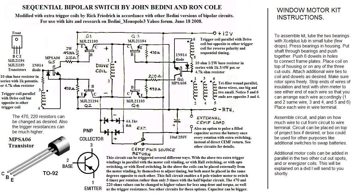
BTW, for reference, here is the Bedini "sequental bipolar circuit":
Hob Nilre
http://www.youtube.com/nilrehob
Comment
-
OH ok. I got ya.
They are 2 different things. I can't speak for that circiut. I haven't built one.
The picture attached is what I stick with. A 4+ battery setup. They may very well have similarities but I think the intention of them is different. You have kinda tried to short cut without first building the original.
There are some short cuts but I have not found them published. And so far I have not found the right components to make any real power.
Sorry I can't be more help on that.
Matt
OOps my attachments are full
Last edited by Matthew Jones; 05-28-2009, 01:52 AM.
Comment
-
Well, maybe I'll try my circuit someday, there are only some resistors missing and probably four of the diodes are unnecessary.Hob Nilre
http://www.youtube.com/nilrehob
Comment
-
What is your current circuit on which you apply the above stated frequency?Originally posted by Matthew Jones View Postbut as the rate of switching gets higher it starts to act different. Around 500hz. I wanna run it in the 100+ khz range
I'm trying to buil a Tesla switch myself and am looking for some build examples, maybe you already showed the circuit in that case I must have overlooked it.
Comment
-
Its pretty hard to get to much faster than about 200-400hz with a mechanical and without prescision machining on your communtator you run the risk of shorting out the circiut. It also requires alot of adjustments.
The semi solid state is the closest thing I have been able to get that will be able to perform at real high speeds.
I haven't published it because I need to have more time to work on it and test it, make sure there aren't problems. Also want to incorpaerate some adjustments for speed.
I am in the middle of building my first really sustainable home, and I don't have the time work on anything but it. Its my priority right now.
The best thing you an do is start with a small mechanical, or relay based switching setup. 6 pole relays with small batteries can give you pretty good setup. If you need specific'c search for a post titled "24volt scooter" or somthing like that, I posted a schematic there.
Ask all the questions you want. I'll try to help.
Matt
Comment
-
We know that sparks and arcs cause interesting events. They cause dipoles.Originally posted by Matthew Jones View PostIts pretty hard to get to much faster than about 200-400hz with a mechanical and without prescision machining on your communtator you run the risk of shorting out the circiut. It also requires alot of adjustments.
The semi solid state is the closest thing I have been able to get that will be able to perform at real high speeds.
It may be that the mechanical interrupting has to do with the effectiveness and that transistor switching will spoil or reduce effects. Certainly this was the view of Patrick Kelly at last year's UK Free Energy Conference.
Paul-R
Comment
-
You get a dipole when you ask for a charge from generator of some kind and/or battery. Sparks are sign of killing the dipole. Not always but most of the time.We know that sparks and arcs cause interesting events. They cause dipoles.
The relays and or transistor switching has nothing to do with anything. You need speed. And drivng that circuit that fast without grounding the current is hard to do.
A semi mechanical switching setup can do it. But how fast depends on the communtator and its accuracy.
The switch's can be transistors driven by the mechanical switch.
The thing to understand is you cannot drive the ground side switch's with the hot side power attached to the base or vise versa
Bedini does outline the simplified version. You can get that running pretty easy with multivibrator circiut and 3 double poled relays. The problem is getting the relays big enough for a sizable load. And if you want to go to higher speed your bound to the relays MAX.
Ah, I bablinbg on...
Cheers
Matt
Comment
-
Heya mathew.
No no no you are not babling. You are helping us to understand what is going on.
On a second note you are very correct that the requirements for the relays are the limiting factor. One thing you can do is actually reduced you load! The motor is the key here and there is a new motor on the horizon that might help with that. It is called a flux gate motor and is currently being developed by Hilden-Brand. What it does is actually direct the magnetic flow of two banks of very strong magnets to a central position causing rotation of the rotor with the combined magnetic attraction of the banks of magnets with lower current coils. here is a picture for you to check out the design. This might be the key to cut down the current required to activate the flux gate and hence lower the current that needs to pass thru the relays and still have great power to boot.
Picture: http://i128.photobucket.com/albums/p...xgatemotor.jpg
Blue is energized coils and red is normal off coils.
It is kinda a leeskalnin design or based off that design. It might be interesting to further study this and see if improvements could be made to facilitate a lower requirement for switching so relays could be used without burning them out.
I tried asking everyone before what they thought about this design but no one really replied... weird...Last edited by Jbignes5; 06-07-2009, 01:39 PM.
Comment

Comment