This forum is preserved as a permanent archive. The community continues at eMedia Press.

Announcement

Collapse
No announcement yet.

The Solenoid/Electromagnet

Collapse
X
 
  • Filter
  • Time
  • Show
Clear All
new posts

  • #31
    Originally posted by wrtner View Post
    This is nonsense. Look at the work of the massive Tesla coil builders
    and even the front cover of "Wheelwork of nature":
    Valone harnessing the wheelwork of nature - tesla's science of en...

    It is easy enough to sketch a bilar traditional coil. If he had
    meant that, he would have done that.
    Can you show us where it is stated that all other coil types are excluded.

    I can show where they are included.

    From the patent.

    Patent US512340 - NIKOLA TESLA - Google Patents

    Lines 32 to 38

    I would here state that by the term coils I
    desire to include generally helices solenoids
    or in fact any conductor the different parts
    of which by the requirements of its applications
    or use are brought into such relations
    with each other as to materially increase the
    self induction
    .
    Lines 39 to 45.
    I have found that in every coil there exists
    a certain relation between its self induction
    and capacity
    that permits a current of given
    frequency and potential
    to pass through it
    with no other opposition than that of ohmic
    resistance or in other words as though it possessed
    no self induction.
    It's all there if the patent is read, I see no need for argument about this, it
    means for all coil types. and says so in the patent. People don't get to make
    the patent mean what they want it to mean. It means what it means in plain
    old english.

    Cheers

    Comment


    • #32
      Riddle.... how is that related ? http://jnaudin.free.fr/images/tbfnrganm.gif

      Comment


      • #33
        Originally posted by Hrothgar View Post
        The pancake coil itself may have been illustrated mainly for communication, the visual of the wire turning back on itself is probably easier to understand this way.
        i dont think this is correct, if it was, why would Tesla himself have not 1 but 2 bifilar pancake coils made in the same way? the first was destroyed in fire and he rebuilt the second in his new work shop. if it was only for show, why did he think it was important to have them and use them?
        to really understand a pancake coil and see its potential, you need to build it

        Comment


        • #34
          @Farmhand
          It's all there if the patent is read, I see no need for argument about this, it means for all coil types. and says so in the patent.
          If the patent is read... in fact I have found most of the critics never actually read the literature they are critical of which is kind of comical when a person thinks about it. Proclaiming their opinion as fact then getting caught with their pants down, lol, at some point you would think they would learn ... apparently not.

          AC

          Comment


          • #35
            Bifilar Electromagnet

            I found a page where someone also compared field strengths of bifilar coils compared to single wire coils. They also state that the magnetic field is stronger.

            I really wish that video on youtube wasn't taken down. But then again I've posted it 3 times on this forum over the past year without anyone so much as glancing at it, so it's not my fault if people just refuse to see something extremely significant in our line of work...........

            Comment


            • #36
              excellent

              thanks for the link chain

              Comment


              • #37
                Originally posted by chainmailleman View Post
                Bifilar Electromagnet

                I found a page where someone also compared field strengths of bifilar coils compared to single wire coils. They also state that the magnetic field is stronger.

                I really wish that video on youtube wasn't taken down. But then again I've posted it 3 times on this forum over the past year without anyone so much as glancing at it, so it's not my fault if people just refuse to see something extremely significant in our line of work...........
                That experiment was done by at least two people over at OU.com and when
                the same amount of wire and turns was used for both coils the magnetic field
                strength was the same. I would encourage doing the experiment yourself.
                Remember to de magnetize the nails between tests. You tube video's like that
                can be fudged in a number of ways. I don't trust them, but I do trust Gyula
                who first did the experiment with uninterrupted DC.

                Cheers.
                Last edited by Farmhand; 07-09-2013, 07:54 PM.

                Comment


                • #38
                  Originally posted by Gav View Post
                  i dont think this is correct, if it was, why would Tesla himself have not 1 but 2 bifilar pancake coils made in the same way? the first was destroyed in fire and he rebuilt the second in his new work shop. if it was only for show, why did he think it was important to have them and use them?
                  to really understand a pancake coil and see its potential, you need to build it
                  Those were single filar radio transmitter or magnifying transmitter coils. And
                  he built way more than just two. I've built more than two flat spiral coils. In
                  some situations a flat spiral coil is desired like in an induction cooker. An
                  induction cooker uses a HF flat spiral electromagnet, but they don't use bifilar
                  wound electromagnet that I have seen. One situation where an electromagnet
                  uses other than uninterrupted DC.

                  The coils for electro-magnets patent relates to bifilar wound coils in an
                  inductance aiding configuration. The radio coils were just one winding.

                  When we speak of electro-magnets we should differentiate between regular
                  "electro-magnets" and "electro-magnets for lifting" or lifting electro-magnets.

                  Flat spiral coils have their uses but they are just coils, they are not magic.

                  The coil for electro-magnets patent is not about lifting magnets as such. But
                  it is definitely about negating reactance, which is not an issue with
                  uninterrupted DC. So it's about pulsed and AC magnets.

                  A field coil for a motor or generator can be one form of pulsed electromagnet.

                  Things to remember is that the patent not about DC magnets and it's not
                  about lifting magnets only.

                  Cheers
                  Last edited by Farmhand; 07-09-2013, 07:50 PM.

                  Comment


                  • #39
                    Originally posted by Farmhand View Post
                    That experiment was done by at least two people over at OU.com and when
                    the same amount of wire and turns was used for both coils the magnetic field
                    strength was the same. I would encourage doing the experiment yourself.
                    Remember to de magnetize the nails between tests. You tube video's like that
                    can be fudged in a number of ways. I don't trust them, but I do trust Gyula
                    who first did the experiment with uninterrupted DC.

                    Cheers.
                    And I have conducted the experiment myself using the same amount of wire and the same power supply and came to a very different conclusion. I did not use nails, I used a compass. Nails are another way to go but a compass is far more accurate. You will see a gain in field strength. 1 coil with 100 turns of wire is equal to 2 coils with 50 turns of wire on the same diameter core.

                    If everything on youtube was fudged, faked, or make believe, how come Eric Dollard is on there?

                    Comment


                    • #40
                      bifilar vs. standard winding

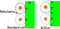
                      I've noticed something about the pancake style coil, from the spin of the magnetic force in the wires it appears that the coil fields would resemble a north/south Halbach array. The north south Halbach increases the density restricting the flux field to a small area. Has anyone been able to measure if the field size and shape between the two coils differ?

                      PS the green in the picture represents a core
                      Attached Files

                      Comment


                      • #41
                        Simple view

                        Hi All
                        I am reluctant to enter into this debate, but I am sure some clarity should be shown.

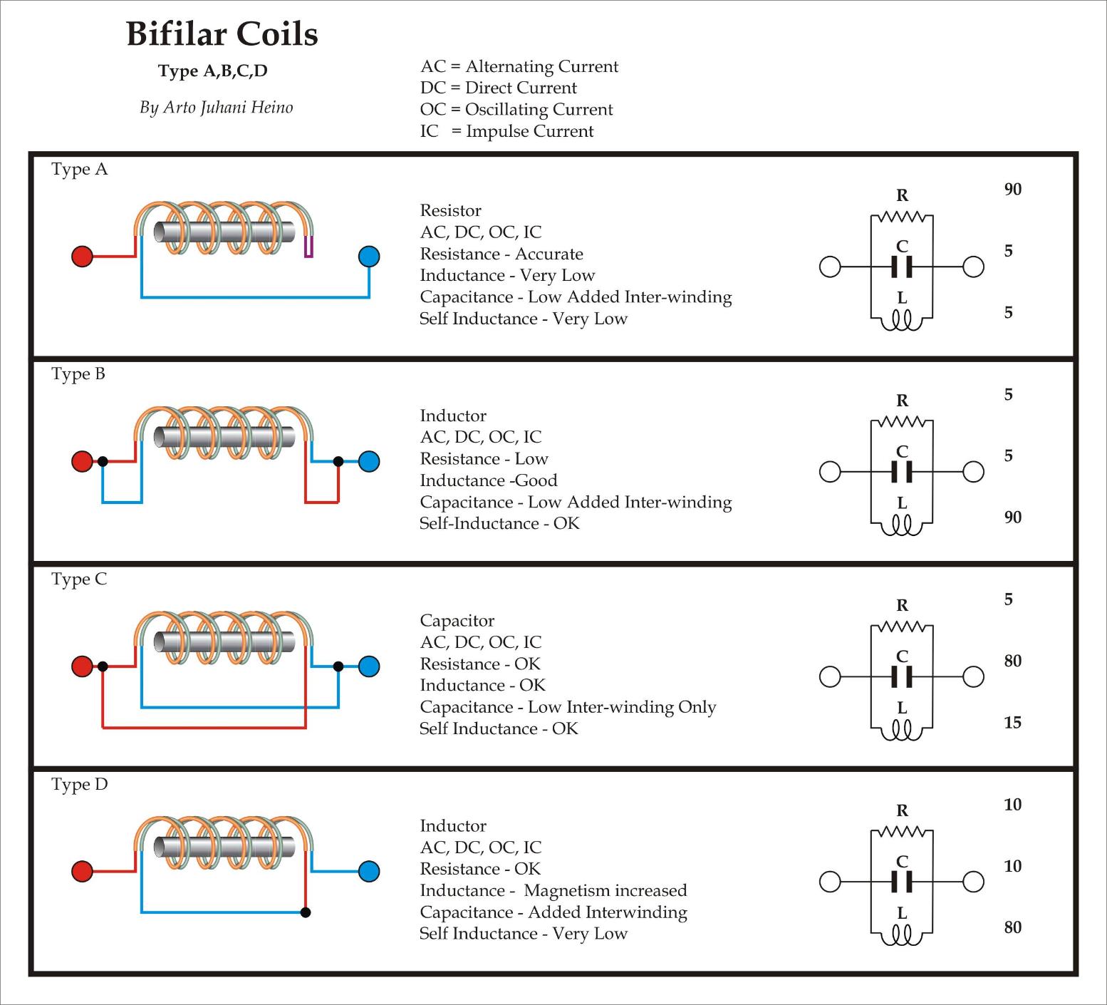
                        It seems some folks think that the Bifilar Tesla arrangement has magical properties, Farmhand said it plain and clear, read the Patent. I have been designing wire coil arrangements for most of my life. The only advantage you gain from any system is one you engineer from its different properties that is understood, no magic just simple electrical engineering. The bifilar arrangements are of 4 basic types, with the others being transformer types when using 3 or 4 connections.

                        He is the simple 4 types, all properties have not been accurately analyzed with differing parameters yet(this diagram is cursory only). The cancelling self induction of Type D (Tesla), can only happen when the coil is AC,OC or IC, DC will only show differences on the charging or discharging curves. This is exactly as Farmhand expressed, this can only born out of experience not conjecture.


                        The geometry and the advantage of pancake types coils is one of dimensional usage, the shape of the field and the compact form. It is no better than any other coil form only another option when engineering a design. It will have differing geometries and some EM properties than another form, this is how I see its place, only as part of an array of useful tools that are at our disposal.

                        I hope this helps, Regards Arto.

                        Comment


                        • #42
                          Type D is the configuration in question. And as your picture states, the magnetism increased. The problem is why? The current has not increased as the resistance is the same as a single wire coil. Conventional thinking equates magnetism with current...so why the increase in the magnetic field with no apparent increase in current? (Ohm's law, the wire is a resistor)

                          Magical or not, where is the math to explain this phenomena of increased field strength?

                          Comment


                          • #43
                            Mutual

                            Hi, Please verify all parameters by building test coils, this should help those who cannot see the simplicity of what Tesla has shown.

                            It is not the increase of field strength when you energize the coil with an AC,IC,OC input, it is the simple result of reduced reluctance in its inherent geometry, it acts in mutual inductance to the second winding reinforcing its magnetic component.

                            As I shown you dealing with 2 coils that interact in a different manner than 1 single coil, this term is called mutual inductance. Self Inductance is the only term you normally deal with in single coil calculations, this parameter changes drastically when 2 or more coils are in an arrangement. I have another chart that can help you see that the geometry is what makes the difference. refer to my post


                            You can see that the Type D coil has a similar geometry to the B2 coil coupling arrangement, only the bifilar type has a very close mutual inductance. The other interesting note is the potential difference between windings in a Tesla bifilar coil, again this is the result of geometry and close coupling resulting in a low self inductance. What you change in one variable you will see a change in another, all becomes equal in the balanced equations.

                            Because the different windings has the effect of the changing the distributed capacity of the coil it will also change the coils performance parameters. The effect of the Self Resonant Frequency increases the effective inductance so it appears higher than the true inductance. If an inductor has C1 of distributed capacitance, the actual resonating capacitance needed for a particular frequency would be C1 lower due to the distributed capacitance. Therefore the effective inductance appears as if it were higher than measured. Again this means a variation that has consequences due to coil geometry alone.


                            Le = effective inductance
                            Lm = measured inductance
                            F = frequency target
                            Fr = self resonant frequency

                            Le = Lm / (1 - ( F / Fr )^2

                            (reference Arthur Williams)

                            Steinmetz, Kron, Bewley and Dollard are required reading when it comes to understanding the exchange of energy in a circuit. Please check out their analysis if coils and such, you should find all the equations for these interactions.

                            I hope this helps Regards Arto.

                            Comment


                            • #44
                              That does help tremendously in another topic of personal interest in transients as I am familiar with Steinmetz and Dollard.

                              However I don't think my problem was worded correctly. I am looking for the formula for calculating the field strength of a DC series-connected bifilar electromagnet. The formula you provided gives Le/1, which does not add up with my observations. My experimentation (and that of others) shows about 3/4 or 75% gain in comparison to more conventional configurations. Since there is no real change other than the initial connection, and the current remains the same, and the number of copper turns remains the same, how come the field is stronger? How come when capacitance is added, the coil prefers to store the energy in the magnetic field other than the dielectric field? This is what confuses me about this coil configuration.

                              Comment


                              • #45
                                I've been trying to edit my post.

                                My edit:

                                Lm/1 instead of Le/1

                                Comment

                                Working...
                                X