

 Tweet
Tweet
Hi chainmailleman, What you are looking for is an equation, you should be able to deduce this from your experimentation that you have performed. If that is not possible please list all your data and include your data that verifies your conclusions so we can all pitch in and help. Regards Arto
-
-
Hi Arto,
I have just seen your nice chart on the bifilar coil configurations with their salient features. I agree with them, except for the self inductance of type D configuration: why you wrote self inductance is very low?
You qualified it just like for type A where self inductance is indeed very low due to the electric currents (so their fields) work against each other in the parallel wires. In my practice, I found almost 4 times (mostly 3.8 times) as high self inductance for type D than that of any one of the coils individually constituting the bifilar windings i.e. either the yellow or the gray colored winding in itself. I would appreciate your comment on this.
Thanks, GyulaComment
-
Hi gyula, not quite finished with the drawing , as quoted "all properties have not been accurately analyzed with differing parameters yet(this diagram is cursory only)". If you have some data, please list it here so we can verify and extrapolate an equation. Regards Arto.Comment
-
I think this is most unlikely.Originally posted by artoj View Post
These Aussie freaks, http://tesladownunder.com/ , speak of the problems of winding these nuisance coils and would not bother if they could crank out regular bifilars and get the same results.
Tesla designed them flat because, for his purposes, they need to be flat.Comment
-
none of you addressed my question as of yet...
is someone going to answer it? I was talking about individual behaviour of the spin against the core.Comment
-
Hi Arto,Originally posted by artoj View Post
Okay, I understand. I have some measured self inductance values on single and bifilar windings, using the same length of wire for both. I can quote from my post at another forum. Here are my findings:
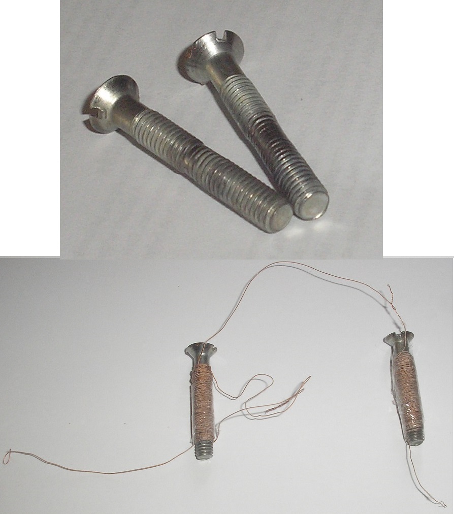
I used two identical sized bolts M6x40mm (i.e OD 6mm length 40mm) for the coils core. I used two 6 meter long enamelled+silk insulated copper wires, OD 0.3mm (awg #29).
I wound one 6m wire as a single wire onto one of the bolts, lets name it bolt1, it has about 136 turns, DC resistance is 1.6 Ohm, inductance is 416 uH.
I folded into half the other 6m long wire and wound the two parallel wires onto the other bolt, let's name it bolt2, it has about 68 bifilar turns, then I identified the wire ends of the coils on bolt2 and connected the end of the first wire to the start of the second wire. Thus the two wires in series have DC resistance also 1.6 Ohm, inductance in series is 423 uH, individually each coil is about 107uH.
When these two latter coil wires are unconnected from the series aiding fashion, the capacitance between either the two wire ends or between the wire starts is measured as about 220 pF with a C meter.
Obviously, the tiny difference between the inductances on the two bolts (416 uH and 423 uH) can be explained by any difference in the permeabilities of the bolt materials.
So the ratio in this case is 423uH/107uH=3.95 this can confirm the 4 times increase for the series connection of bifilar windings in aiding phase.
When I connected them as per your chart shows at type A, then I Measured this coil with an L meter, it showed a fluctuating value between zero and 1uH. When I short circuit the L meter input with a thick piece of short wire it measures zero, unfortunately the most sensitive range it has is 2mH, so this coil must have a less then 1uH inductance.
Will add some more comments later.
GyulaLast edited by gyula; 07-10-2013, 03:48 PM.Comment
-
I don't think a tangential force on a compass can give us an exact figure to use. A better setup would be a spring scale attached to the iron plunger. (Example of my data: Single wire wound coil 50 turns @ 12 volts with 15 ohm resistor in series gives 2 degrees deviation. Bifilar Parallel configuration at 25 turns per coil at 12 volts with 15 ohm resistor in series gives 2 degrees deviation. Bifilar series configuration at 25 turns per coil at 12 volts with 15 ohm resistor in series gives 3.5+ degrees deviation. Coil resistance measurements were .3 for parallel and .5 for single wire and series).Originally posted by artoj View Post
A different experiment I observed with a 12 volt battery charger. The compass obviously moved a much larger distance as no resistor was used in series to limit the large currents. The deviation on the compass was about 35 degrees for parallel configurations, and 50+ degrees for series connections.
Then you have paperclips from the site posted earlier, which they give conclusions, not data.
A yahoo group mentioned these coils get about 75% gain from 2 people claiming a similar experiment.
The problem is the experiments were to see what field is stronger, not a measurement of the strength of the field in a given unit of measure. I do not currently have access to my equipment, or materials to make a measured experiment. I'm quite frankly shocked to see so few have literally tripped over this interesting phenomena enough to give it some detailed experimentation.Comment
-
Hi gyula,
Thanks for those measurements, this is what I have worked out so far:
Using this equation;
L = ( u0 x ur x N^2 x A )/ Ln Henry
Bolt1
u0 = 4 x pi x 1e-7 Magnetic permeability constant
ur = 6.4 Relative permeability of Bolt
N = 136 Number of turns
A = 0.0001130973 Area of core sqr mtrs
Ln = 0.04 Length of core mtrs
L = 420.591 uH ( micro Henry)
Bolt2 (half winding)
u0 = 4 x pi x 1e-7 Magnetic permeability constant
ur = 6.4 Relative permeability of Bolt
N = 68 Number of turns
A = 0.0001130973 Area of core sqr mtrs
Ln = 0.04 Length of core mtrs
L = 105.147765 uH ( micro Henry)
The ur seem a little low, what sort of material are the bolts. Also is the length of winding on the coil 40mm same as the bolt? Regards ArtoComment
-
Hi Arto,
I have no idea on the material the bolts were manufactured from, they must be at least 25 years old from a junkbox and very much abused as you can see in the attached picture. I picked them randomly, observing the same types and sizes by sight, hoping for similar permeabilities. The length of the winding is shorter than the full 40 mm, it is about 30 to 32 mm. I agree the permeability comes out a little low, maybe the Carbon content of the steel and wearing could explain it.
Regarding the math on the mutual inductance of the bifilarly wound coils, it seems okay to explain the nearly 4 times increase because twice of the mutual inductance should be added to the sum of the individual winding inductances to get the total, L=L1+L2+2M when the windings are in series aiding phase connection and in close proximity. Here is a link to this: Inductors in Series and Series Inductor Circuits near to the bottom of the page but you surely know this topic.
I recall measurements on a single and a bifilarly wound air core solenoid coils, done by Nichelson, using a HP network analyser. See this PDF file: http://home.comcast.net/~onichelson/VOLTGN.pdf from his site: https://sites.google.com/site/teslanichelson/
Interestingly, he compares the quality factor, Q=XL/R of the single and the bifilar coils and he calles the Q as voltage gain. His single wire coil (207.9 uH) gave a resonant frequency at 19 MHz with its own self-capacitance while the bifilarly wound coil (205 uH) gave him a resonant frequency at 11 MHz with its own self cap. This latter frequency shows that the series bifilar coil has a higher self capacitance than the single wire coil has because for the same number of turns and shape factor the bifilar coil has a much lower self resonant frequency than the single wire coil.
So he found that the calculated and measured voltage gains differ as many as 929%. Practically the measured unloaded Q of the single and bifilar coils are involved and for applications that can preserve the high unloaded Q, the bifilar wound coil seems to have advantage.
Nichelson also mentioned the bifilar coil in this paper too: http://home.comcast.net/~onichelson/Thermodynamics2.pdf Page 6 and 7.
Quote from Page 6: "A bifilar coil is capable of holding more charge than a single wound coil. When operated at resonance, the distributed capacitance of the bifilar coil is able to overcome the counter force normal to coils, inductive reactance. It does not allow what Tesla described as the formation of 'false currents'. Because the electrical activity in the coil does not work against itself in the form of a counter-emf, the potential across the coil quickly builds to a high value. The difference between the turn becomes great enough that (Tesla, 1892) "the energy would be practically all potential." At this point, the system becomes an electrostatic oscillator. "
And here comes a text what I can consider as speculation by Nichelson:
"Minimal work is done in the system due to absence of translational movement in the displacement current. As small heat losses occur, oscillations are maintained by the surplus charge stored in the coil. Very low energy expenditure allows power delivery to a load over an extended time period without an external fuel supply. After an initial input of energy from an outside source, Tesla's new electrical generator would operate as a fuelless device."
IT would be good to learn about such applications Tesla took advantage of as he defined his claims in his Coil for Electromagnets patent.
rgds, GyulaAttached FilesComment
-
-
Hi chainmailleman,Originally posted by chainmailleman View Post
Do you mean for instance that using a Gauss meter would be a much better estimate of the strength of the fields?
Could you accept tests done like the paper clip tests but performed more thoroughly?
If yes, here is my tests shown on another forum, you do not have to log in to see them.
Paperclip test:
Confirming the Delayed Lenz Effect
Repeated test with small nuts instead of paper clips:
Confirming the Delayed Lenz Effect
And my third test on a bifilar coil Arto showed in his chart as type A:
Tesla's "COIL FOR ELECTRO-MAGNETS".
Another member, Magluvin also replicated the electromagnet tests with the nails, see his post here:
Tesla's "COIL FOR ELECTRO-MAGNETS".
So what I found was that there is no difference in holding force: the bifilar coil (connected as per Tesla wrote in his patent) performed the same as a non bifilar electromagnet coil did, having the same wire length, coil geometry and core. Member Magluvin also found no difference in holding force between them.
I would like to read about the yahoo group members how they performed the tests if they described them.
Thanks, GyulaComment
-
Please don't attribute to me things I did not say.Originally posted by chainmailleman View Post
I didn't say everything on you tube is faked or fudged. I said things on you
tube can be fudged and faked, which is a very different statement.
I get suspicious when people put words into my mouth that I didn't say to try
to make a moot point. It's creating a comment I didn't say to dismiss me.
I have video's on you tube and so does MIT. Many genuine and honest people
have video's on you tube.
Why bring Eric into it anyway. But since you did why don't you ask him to
clarify the situation.
Regardless, I'll go by the patent and the experiments of those I trust as well
as my own and plain old logic.
It's such an easy experiment anyone who doubts Gyula's or anybody else's result for that matter should do the experiment.
Cheers
P.S. We need to remember folks that the conductor spacing(insulation thickness)
and the voltage used also affects the self capacitance secured and therefore
the resonance frequency. This seems to be overlooked and I think to be
scientific it must be considered. The voltage used and the insulation
thickness/conductor separation will affect the optimum frequency of operation.
...Last edited by Farmhand; 07-10-2013, 10:31 PM.Comment
-
Yes how rude of us all. I can't give a real answer, but I must say it is interesting.Originally posted by Hrothgar View Post
I thing the adjacent wires in a Coil for Electro-magnets have the same spin direction just like a normal coil but the potential difference is greater.
CheersComment
-
Ohh...
I saw it wrong. So in essence(if I got this right) the biflar coil has a dominant drive coil and a submissive recycle coil. The submissive coil is strong enough to keep containment on the core but not strong enough to exert excessive reluctance on the dominant coil.
Comment
-
Comment
-
dependancy issues
artoj, I figure that type D depends heavily on a solid core for optimum effect. However, how dependant are the other 3 types? A for instance being the resistor it would appear to me that it would be heavily dependant on a core as it looks like the magnetic orbits would otherwise appear sympathetic and free wheeling.
Comment
Comment