This forum is preserved as a permanent archive. The community continues at eMedia Press.

Announcement

Collapse
No announcement yet.

Electromagnetic Induction in Solenoid Generator Coils

Collapse
X
 
  • Filter
  • Time
  • Show
Clear All
new posts

  • #61
    A video is being uploaded...

    Place your bets now! lol


    Originally posted by ren View Post
    You know what Sep, I have been thinking about this. I think it has alot to do with the geometries of our setups. When the magnets pass the windings on my window motor they are triggered to fire, and they dont fire when the magnet is in the middle of the window winding (This is true if the winding is not a conventionally wound winding, and is placed around the circumference still in window form). But if you have a rather large solenoidal coil and a much smaller magnet on the rotor it would pass one side of the coil before reaching TDC,or the core, and then pass the other side of the coil before leaving on its way. Of course the wave form might look different if the coil was the size of the magnet (i.e large magnet small coil), but I think I understand your stance.

    @ Cody. Air core motor is easy enough. You shouldnt have any problems.

    @ all. What is the core really? Is it the opposite of what is flowing through the windings? In an air core coil (or any coil really) isnt the space outside the conductor just as important as the conductor itself? One being the opposite of the other?
    Ren, I agree it is the geometry... but with a solenoid TDC will always be the Zero Volt mark. As I said earlier when a magnet passes one side of a window coil the maximum voltage is generated. But what if a north pole passes both sides of a window coil at the same time? No current will be generated because they will be generating voltage in opposite directions...

    Comment


    • #62
      YouTube - Sephiroth versus the DarkWizard!

      Coming to a cinema near you...

      Comment


      • #63
        Your time is limited, so don't waste it living someone else's life. Don't be trapped by dogma — which is living with the results of other people's thinking. Don't let the noise of others' opinions drown out your own inner voice. And most important, have the courage to follow your heart and intuition. They somehow already know what you truly want to become. Everything else is secondary.

        Steve Jobs. Apple CEO

        Comment


        • #64
          Theorizer are like High Voltage. A lot hot Air with no Power behind but they are the dead of applied Work and Ideas.

          Comment


          • #65
            Maybe!!!!!

            As i read ,i think that the best way to recover the volts is to have bifiliaire
            coil with a diode at the start and on the second coil have a diode at the
            end.....
            This way you utilize the coil to the max!!
            And combining both battery,you can have longer life...Is`n it?????

            Just a tought..

            Alain D
            Hope die last!!!

            Comment


            • #66
              Not at my Circuit.
              Theorizer are like High Voltage. A lot hot Air with no Power behind but they are the dead of applied Work and Ideas.

              Comment


              • #67
                I could not see what are you testing with that leds.

                Comment


                • #68
                  BY JOIT Well i played a bit around with Magnet and a Aircoil too.
                  At ideling, the Coils makes a plane Line,
                  when i move the Magnet over, the Curve increase to a Top Point, then it make the Sinus Wave.
                  Would the Current induced at the Top Point, then the Wave should start there too, am i right?


                  Please explain Joit

                  Comment


                  • #69
                    Ha Ha Ha Phase shifting problems

                    see this document http://www.controlledpwr.com/whitepapers/ipphasa3.pdf

                    Sephiroth i think that you have part of the true, but you refuses to find a solution to the problem.
                    Last edited by darkwizard; 01-27-2009, 05:44 PM.

                    Comment


                    • #70
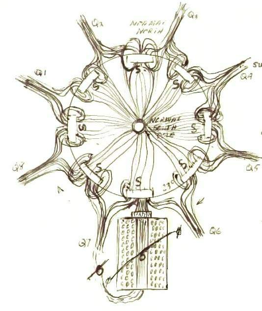
                      I have always liked this picture!!!!
                      Attached Files

                      Comment


                      • #71
                        Originally posted by darkwizard View Post
                        Ha Ha Ha Phase shifting problems

                        see this document http://www.controlledpwr.com/whitepapers/ipphasa3.pdf

                        Sephiroth i think that you have part of the true, but you refuses to find a solution to the problem.
                        As far as I am aware the Phase-Shift you are refering to applies to transformers and not generator coils. Can you find a source that refers to phase shifting in a generator coil as the link you have provided is also refering to transformers...

                        I could not see what are you testing with that leds.
                        Do you understand how a strobe works?

                        Comment


                        • #72
                          This image is a bit clearer...


                          now look at the schematic I have used for the generator coil and try to understand why those lines show up the in the places they do.

                          Comment


                          • #73
                            Seph,
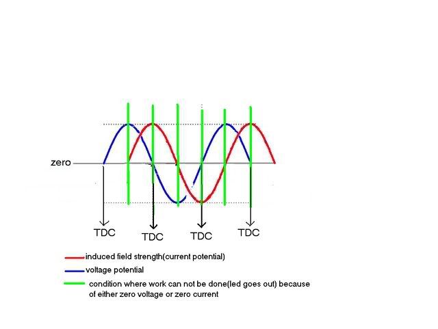
                            The phase shift between current and voltage makes perfect sense to me. It is clearly shown in the link you provided yourself to the basic ac generator. There you see voltage out of phase with induced field strength. Magnetic field strength is always associated with current, not voltage. Therefore, when the magnet is at tdc, you have the highest potential current with zero potential voltage. As we get farther away from tdc, current decreases(field strength) while voltage increases up to the point where voltage is at its max and current is at zero. Your Led video clearly displays this. Work can only be done when voltage and current are present together, so at tdc= no voltage/high current=no light. Beyond tdc there is a period where current and voltage are present together, thats where you are lighting up at. And then further you reach the max voltage point but have no current=no light again. This is behaving just like a pendulum. Max potential on one end(voltage) and max kinetic(current) on the other end. Darkwizard you say no current can flow in an open circuit, that may very well be true, but here we are talking about potential current, not flowing current, in other words it has the ability to kinetic work, we just are choosing not to use it(open circuit). Its like letting the pendulum keep swinging, while it has potential to do kenetic work, we let it keep swinging and choose not to use it. You both have brought up some very good points and they will be very valuable to our understanding of this. Thank you both. Seph here is your picture i modified to show this.
                            Last edited by cody; 01-27-2009, 08:19 PM.

                            Comment


                            • #74
                              Originally posted by darkwizard View Post

                              Please explain Joit
                              Theorizer are like High Voltage. A lot hot Air with no Power behind but they are the dead of applied Work and Ideas.

                              Comment


                              • #75
                                Cody, I see what you are saying but I am not convinced this occurs in the generator coil... You can not have current when the voltage is zero. In the PDF darkwizard linked to it refers to the applied voltage compared to the current, in the example provided by the PDF an AC sine wave.

                                With an AC sine wave (in their example) they show that it is possible for the applied voltage to be zero, yet current is at its highest. This doesn't mean that there is zero volts across the circuit, it means the coil is generating the voltage. Just like in a bedini circuit, when we shut off the transistor the applied voltage is zero, but current still flows through the coil because of the voltage created by the coil.

                                but at least you do agree voltage is zero at TDC

                                I tried to explain that in the diagrams I posted but I will break it down into more detail...

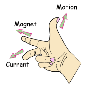
                                This is Flemming's Right Hand Rule


                                Which basicall states that when a north pole is moved over a conductor, current/voltage is generated perpendicular to the movement of the magnet as shown in this image (I have to admit I think I got the voltage wrong in the first photo)


                                so if we move a magnet in parallel across a wire we generate zero volts as shown in this image.


                                Now what if the wire is going in two directions at the same time as shown in this image? (you can assume the wires are twisted together to make it easier)


                                No voltage or current is formed across the two ends of the wire because the wire is conducting voltage in opposite directions. Much like shorting two identical batteries together in parallel.

                                Now how does this apply to a solenoid? Look at the image closely... the grey arrows refer to the direction the wire is in on either side of the solenoid...


                                Now look at this photo again and notice exactly where the lines are in relation to the windings...


                                Come on guys...

                                Last edited by Sephiroth; 01-27-2009, 09:18 PM. Reason: said magnet but meant solenoid

                                Comment

                                Working...
                                X