This forum is preserved as a permanent archive. The community continues at eMedia Press.

Announcement

Collapse
No announcement yet.

Eric Dollard

Collapse
This is a sticky topic.
X
X
 
  • Filter
  • Time
  • Show
Clear All
new posts

  • #61
    Law of Electro-Magnetic Induction, Seven (1 of 3)

    (1) Magnetism is a product of two factors;

    One, the Magneto-Motive Force, is, in Ampere-Turn,

    Two, The Magnetic Inductance, L, in Henry.

    Variation of one or both of these factors results in the variation of the quantity of magnetism. In turn this variation in magnetism develops and E.M.F. in direct proportion to the time rate of this variation. This E.M.F. is developed thru Parameter Variation.

    Variation of the parameter magneto-motive force is brought about by the variation of the current, i, in ampere which produces this M.M.F. The M.M.F. and its current are related by,
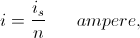


    Or,
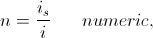


    Where

    n = Number of Turns.

    This number, n, is the ratio of M.M.F. to its current, and it serves as a magnification factor for current flow.

    Variation of the parameter Inductance is brought about by the variation of the factor
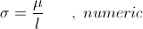


    Where

    is the magnetic permeability, in centimeter

    is the magnetic path length, in centimeter.

    This factor, , is the effective permeability of the magnetic circuit. The magnetic permeability is a characteristic of the medium which supports the magnetic induction. This is not to be confused with the relative permeability. The magnetic permeability

    , centimeter

    is an Aether constant derived from One Over c Square. The relation is given by,



    Where



    c is the Velocity of Light.

    Hence the relation is given as



    This is the magnetic permeability. In order to simplify mathematical expression the relative permeability is often used. It is given by the relation


    Where

    is the magnetic permeability of free space or the Aether. Here then exists three expressions for permeability;

    One, Magnetic Permeability,

    , Centimeter,

    Two, Effective Permeability,

    , Numeric,

    Three, Relative Permeability,

    , Numeric.

    SUPPORT ERIC DOLLARD'S WORK AT EPD LABORATORIES, INC.

    Purchase Eric Dollard's Books & Videos: Eric Dollard Books & Videos
    Donate by Paypal: Donate to EPD Laboratories

    Comment


    • #62
      Law of Electro-Magnetic Induction, Seven (2 of 3)

      (2) The general expression for magnetic inductance is given by the relation,


      Where

      A is the sectional area of the magnetic induction, in centimeter square


      is the total flux inter-linkages between the current, in, Number of Turns,


      A, Sectional Area,

      , Path Length,

      , Magnetic Permeability.

      The number of turns, and the sectional area are in general invariant. The number of turns is fixed by the impedance, and the sectional area is fixed by the volt-ampere capacity. The path length can be variable by mechanical means. The magnetic permeability can be made variable by magnetic means.

      The path length and the magnetic permeability are directly related as they have the same dimension, centimeter. They are both lengths, and their ratio is the effective permeability. This is the parameter to undergo variation.

      (4) Permeability works thru the dimension of length, here in centimeter. The length of a magnetic flux line determines the amount of M.M.F. required to maintain that length. A force is required to hold this line in place. The more the flux line is stretched out, the greater the M.M.F. required. This determines the magnetic gradient along the flux line as,


      The flux lines are elastic, if stretched out, they hold the energy required in this stretching and it returns when the stretching force is withdrawn. During the interval in which the flux line expands or contracts an E.M.F. is developed to facilitate the movement of energy into, or out of, the elastivity of the magnetic flux line.

      If now the magnetic permeability is made to increase, the M.M.F., and thus the current, required to maintain a flux line at a certain length is decreased in proportion to the increase in permeability


      Hence the magnetic permeability acts to shorten the lines of magnetic induction. This is to say that the magnetic permeability allows the magnetism to contract into it. In a magnetic path of centimeter length, a path of high permeability has a much longer effective path length than that of a low permeability. The relation is given as

      SUPPORT ERIC DOLLARD'S WORK AT EPD LABORATORIES, INC.

      Purchase Eric Dollard's Books & Videos: Eric Dollard Books & Videos
      Donate by Paypal: Donate to EPD Laboratories

      Comment


      • #63
        Law of Electro-Magnetic Induction, Seven (3 of 3)

        Where

        is the relative permeability, a numeric proportion. For example, iron has a relative permeability of,

        = 1000 numeric.

        A portion of this iron is in the magnetic path and the length of this portion of iron is,

        = 1 , centimeter

        The effective path length along this iron is then given as


        If this magnetic permeability undergoes parameter variation, it results in an effective variation in path length, this for the Magnetic Induction.

        (5) The effective permeability can be made variable thru mechanical and magnetic means. Variation is produced mechanically by the insertion and removal of permeable material into & out of the path of magnetic induction. This results in the variation of the effective path length, and thus a variation of the effective permeability, .

        In many magnetic materials their magnetic permeability is a function of the flux densities within these materials. The greater the flux density, the less the permeability. When the flux density is increased beyond a certain point the magnetic permeability of the material becomes that of free space. This is known as Saturation. Hereby the magnetic permeable material can be made to vary its permeability by the application of a magnetic field of induction. This in turn gives variation to the effective permeability,
        , and thus a variation in effective path length.

        (6) The general expression for magnetic induction is given by the relation,


        In this relation two parameters can be varied. One is the current can be made variable, in turn giving a variation of M.M.F. The other is the effective permeability can be made variable, this in turn giving a variation of inductance. The current, i, and the effective permeability,
        , undergo variation and give rise to a variation of Magnetism, . This variation of magnetism develops and E.M.F. Three basic relations exist,


        One,


        Two,


        Three,


        These fundamental relations bear resemblance to those of Ohm's Law, as basic expressions of proportionality.

        Relation one expresses a conservation of magnetism, . This gives the Motor-Generator relation. Here an increase in current relates to a decrease in inductance, or an increase in inductance relates to a decrease in current. This proportionality maintains a constant quantity of magnetism.

        Relation two expresses a conservation of Current, i. This gives the variable parameter relation. Here an increase in magnetism relates to an increase in inductance, or a decrease in inductance relates to a decrease in magnetism. This proportionality maintains a constant current.

        Relation three expresses a conservation of inductance. This gives the reactance coil relation. Here an increase in magnetism relates to an increase in current, or a decrease in current relates to a decrease in magnetism.

        In any one of these three various conditions that give rise to a variation in magnetism the E.M.F. which results from this variation transfers energy into, or out of, the Magnetic Field of Induction, . Here derived is a more general expression for the Law of E.M. Induction for the study of parameter variation in electro-magnetic systems.

        BK DE N6KPH
        SUPPORT ERIC DOLLARD'S WORK AT EPD LABORATORIES, INC.

        Purchase Eric Dollard's Books & Videos: Eric Dollard Books & Videos
        Donate by Paypal: Donate to EPD Laboratories

        Comment


        • #64
          Originally posted by jake View Post
          But here is the diagram I was talking about. Does anyone know why in this setup the secondary and extra are joined.
          I believe the "NO METALLIC CONNECTION" was primarily for the testing, this allows us to determine the "maximum" frequency of the coil. That diagram is also lacking the secondary condenser.

          If the extra coil was connected through the condenser rings with NO metallic connection, then you would also need an additional adjustable air condenser across the secondary because I don't think it will be possible to tune the secondary to a low enough frequency with only the extra coil connected through the rings.

          So I think, you will need to play around with it

          [edit] This could be wrong in terms of a proper explanation, but I think there's what could be called something like an "effective coupling capacity" when the thing is in operation. That is, the frequency is raised when the coils are metallically connected, as if an effective coupling capacitance comes into play as opposed to a straight forward metallic connection. So the metallic connection with the secondary is different than the metallic connection in the extra coil test setup.
          Last edited by dR-Green; 07-25-2012, 08:04 PM.
          http://www.teslascientific.com/

          "Knowledge is cosmic. It does not evolve or unfold in man. Man unfolds to an awareness of it. He gradually discovers it." - Walter Russell

          "Once men died for Truth, but now Truth dies at the hands of men." - Manly P. Hall

          Comment


          • #65
            Law of Electro-Magnetic Induction, Eight.

            Magnetic Parameter Variation can be divided into two categories. One is the variation of the M.M.F., thru variation of the Current, i. The other is the variation of the Inductance thru variation of the Effective Path Permeability, . Current, i, and permeability factor, , are the two parameters which can undergo variation in order to give a variation in the quantity of Magnetism, .

            The condition in which only the current undergoes variation exists with the Reactance Coil. Here the inductance is a constant, it is a factor of proportionality. This is expressed in the relation,


            Here a sine wave of current develops a sine wave of magnetism. Both waves exist in a direct proportion, Li, and thus are in phase. Energy is exchanged thru the developed Induced E.M.F.

            Here the Law of Energy Conservation is not satisfied. The Energy given to the Magnetism is not the Energy given back by the Magnetism, there is a gain or loos of Energy. In this situation the Law of Energy Continuity must be considered.

            The condition in which the Magnetism is a constant is the Motor-Generator. This is expressed by the relation


            Here it is both the Current, i, undergoing variation and the Inductance, LRotation of the machine. The Law of Energy Continuity is involved here in that the Mechanical Energy consumed by the shaft re-appears as Electrical Energy produced by the armature windings, this representing a Generator. The reverse is true for a Motor. In each case the form of Energy is not conserved, it is consumed, or it is produced. Thus the Law of Energy Continuity expresses the Energy relationship.

            For the condition of Inductance Parameter Variation and a constant Current the Magnetic Energy is not conserved. While for the Motor-Generator the Law of Energy Continuity is obvious, it is not so for the Parameter Variation apparatus. Here the Law of Energy Continuity is not identifiable, it is somewhat Indeterminate
            SUPPORT ERIC DOLLARD'S WORK AT EPD LABORATORIES, INC.

            Purchase Eric Dollard's Books & Videos: Eric Dollard Books & Videos
            Donate by Paypal: Donate to EPD Laboratories

            Comment


            • #66
              The Law of Electro-Magnetic Induction, Nine.

              The basic characteristics of the Three Principle Conditions has been considered.

              One, The Reactance Coil

              Two, The Variable Parameter Apparatus

              Three, The Motor-Generator.

              For the Reactance Coil it is a sine wave of Current variation, for the Parameter Apparatus it is a sine wave of Inductance variation, and for the Motor-Generator it is a sine wave of shaft rotation, these sine waves give rise to a sine wave of Electro-Motive Force.

              While it is that conditions one and three are generally understood, not so with condition two. The development of an E.M.F. by variation of the Permeability Factor, , is a non-conventional methodology. The most notable apparatus for this purpose is the Alexanderson Alternator. Also the Alexanderson Magnetic Amplifier can serve as a Generator of and Alternating E.M.F. but this has not found practical application. Little exists to facilitate study.

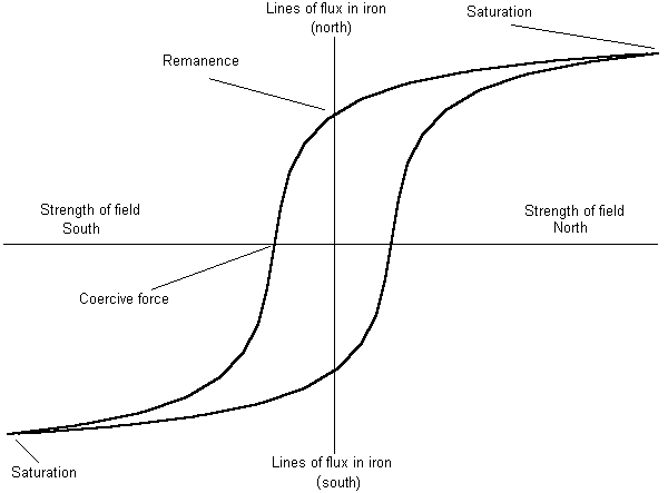
              (1) An example of Magnetic Parameter Variation can be found in the phenomena of Hysteresis. It is a natural phenomena characteristic of certain Magnetic materials, such as Iron. Hysteresis gives rise to an Energy loss in the cycle of Magnetic Induction. For example, if the Reactance Coil has a Magnetic path consisting mostly of Steel, the Energy taken by the Magnetism is not all given back by the Magnetism, part is lost. In conformance to the Law of Energy Continuity it is presumed that the Energy is continued in the form of Heat. Hysteresis results in the heating up of the Steel which makes up the Magnetic path. It was the pioneering work of Steinmetz that led to an understanding of Hysteresis, a major advancement in the engineering of A.C. machinery.

              In general the phenomena of Hysteresis is lumped together with the phenomena of Magnetic saturation. This is an un-fortunate circumstance. While in general the Hysteresis Cycle gives rise to a gain of loss, the Saturation only distorts the wave. The gain or loss of energy is produced by the Hysteresis component of a Magnetic Cycle, not the Saturation component.

              (2) Hysteresis is defined as a Time DisplacementiAngle of Hysteresis, .

              In general if this angle, , Lags, Energy is lost and if it Leads, Energy is is gained, by the Magnetic Field of Induction. The Law of Energy Continuity requires the Energy lost or gained to continue as heat or mechanical activity.

              (3) Let the quantity of Magnetism at any instant in time, or arbitrary phase angle, be represented by the relation,


              If the wave of Current is displaced in phase from its co-responding wave of Magnetism, the Current existing at the time of Magnetism is foreign, it is from another time. The Cause is not present for its Effect. This foreign relation exists thru the Inductance, and the Hysteresis Cycle gives rise to the Variation of this Inductance maintaining the Magnetism at that instant in Time. Thus in the sine wave of Magnetism there exists a co-responding sine wave of Inductance variation, the sine wave of Current will shift in phase to accommodate the sine wave of Inductance variation. This exists in the Reactance Coil with a Hysteresis Loss. Here the sine wave of Current gives rise to a sine wave of Magnetism. This is in phase if the Inductance remains constant. It is however that the Hysteresis gives rise to a sine wave of Inductance variation and this gives rise to a co-responding phase displacement between the Current and the Magnetism. The factor by which Energy is lost via Hysteresis is given by the relation


              Where, , is the angle of Hysteresis, and, a, is the Power Factor of the Reactance Coil.

              In the general situation, if a Reactance Coil exists in which a sine wave of Induction variation is applied, the Reactance Coil can be made to consume Energy for a lagging Hysteresis angle, and to produce Energy for a leading Hysteresis angle.

              BK DE N6KPH
              SUPPORT ERIC DOLLARD'S WORK AT EPD LABORATORIES, INC.

              Purchase Eric Dollard's Books & Videos: Eric Dollard Books & Videos
              Donate by Paypal: Donate to EPD Laboratories

              Comment


              • #67
                Tuning setup for secomdary coil

                dR-Green:
                I have questions about your post #790, dated 6/25/12.
                I have put winding on my newly built secondary coil frame. I have used the 5.5 mm wire spacing first. I have done the tests with just the one condenser ring on top of the frame, connected as Eric specified. Got 3 readings with various can elevation above the secondary. In your post #760 how did you measure the condenser ring to be 11.8 pF? Then when you tuning the extra coil this same condenser ring is now 12.59 pF. I do understand that my condenser ring has different size than yours, but how am I to measure the value(s)? I think I have to play with the distance between the two condenser rings to get the max frequency response. I must be missing something from Eric's extensive instructions.
                Once I do similar tuning as you done in post #790, I will rewind the secondary with 4 mm wire spacing then do all the above described testing and finally rewind again with 3.5 mm wire spacing an repeat the procedure. This way I can verify the best wire spacing for max frequency response. Thank you.

                Comment


                • #68
                  Originally posted by Nhopa View Post
                  dR-Green: In your post #760 how did you measure the condenser ring to be 11.8 pF? Then when you tuning the extra coil this same condenser ring is now 12.59 pF. I do understand that my condenser ring has different size than yours, but how am I to measure the value(s)? I think I have to play with the distance between the two condenser rings to get the max frequency response. I must be missing something from Eric's extensive instructions.
                  Once I do similar tuning as you done in post #790, I will rewind the secondary with 4 mm wire spacing then do all the above described testing and finally rewind again with 3.5 mm wire spacing an repeat the procedure. This way I can verify the best wire spacing for max frequency response. Thank you.
                  I used a capacitance meter Search for "LC100-A" on ebay to find it. It's cheap but very sensitive so pretty good even for measuring the capacitance between the top terminal and the ground plane (although the accuracy of that hasn't been verified, as long as it's constant then it will do nicely for reference).


                  Yes you have to adjust the rings spacing for maximum response. First set your oscillator to "F" or the intended frequency (in my case 3670 kc). Then adjust the rings until you see the peak at that frequency. Now the secondary is tuned for that test.

                  By connecting the extra coil, the secondary frequency is then found to be too high, so the rings capacitance has to be increased.

                  Although this was with the original extra coil wire length with no terminal capacitance, bringing a terminal into the equation complicates it a bit so better if you still have the original extra coil at this point. The rise in frequency will easily be seen.

                  [edit] Otherwise, on capacitance, look at lecture 7 here

                  MIT 8.02 Electricity and Magnetism : MIT OpenCourseWare : Free Download & Streaming : Internet Archive

                  I think it's explained in that, but you might (should) need to get some information from earlier lectures relating to electric charge and electrostatic potential etc. I can't check it now because I'm having computer problems in the way of it turning itself off whenever I try to do something productive

                  Looking forward to seeing the results anyway
                  Last edited by dR-Green; 07-30-2012, 12:58 AM.
                  http://www.teslascientific.com/

                  "Knowledge is cosmic. It does not evolve or unfold in man. Man unfolds to an awareness of it. He gradually discovers it." - Walter Russell

                  "Once men died for Truth, but now Truth dies at the hands of men." - Manly P. Hall

                  Comment


                  • #69
                    Law of Electro-Magnetic Induction, Ten (1 of 2)

                    (1) Hysteresis is described as the separation in time between cause and effect. Cause and Effect relations can be expressed as points on a curve, normally this curve is a straight line. In the graphical representation of electronic devices this curve is called a Load Line. A straight line gives the condition of a direct relation between Cause and Effect.

                    As an example is the condition where the E.M.F., E, is the cause, and the Current, i, is the effect,


                    The Proportionality, R, exists between Cause, E, and Effect, i, and here it is a Resistance. If the Cause, E, is given graphically as a vertical co-ordinate, the resulting Load Line is the graphical plot of the Proportionality between the Cause, E, and the Effect, i.

                    For the condition of a constant fixed resistance, R, in Ohm the Load Line is a straight line. The slope of this line is the instantaneous ratio of the E.M.F. to the Current, and it is constant anywhere along the line. No differential relation exists in that the ratio of any E.M.F. to its co-responding current is always the same value. It is a constant resistance, R.


                    This is known as a Linear relationship.

                    (2) Electrical devices such as Incandescent Lamps or Thyrites do not exhibit a direct relation between cause and effect. For example, the Lamp shows and Increasing Resistance for and Increasing Current, and a Thyrite shows a decreasing Resistance for an increasing applied E.M.F. Here the Load Line is no longer straight, but it is now curved in a parabolic form. The slope is no longer constant but varies with position along the curve. An E.M.F. and its co-responding Current have a different ratio than another E.M.F. and Current taken at another point on the curve. The variation of the slope represents the variation of Resistance,


                    Cause and Effect are now in Dis-Proportion to each other. Here Effect can become exaggerated by the cause and a sine wave of E.M.F. no longer gives rise to a sine wave of Current, distortion results. This is known as a Non-Linear relationship. Magnetic Saturation in Magnetic material is one such disproportional relationship, here between the M.M.F. and the Magnetic Induction, the Load Lines are known as the Saturation Curves of the Magnetic Material.

                    In both the Linear and the Non-Linear relation every E.M.F. has one and only one co-responding current. These exist at one unique point on the Proportionality Curve. The Relationship here is Uni-Valent, or single valued.

                    (3) Another more complex relation can exist between Cause, E, and Effect, iE, there exist two co-responding Effects, or Currents, i. These two Effects exist displaced in Time. Likewise, for each Effect, Current, i
                    SUPPORT ERIC DOLLARD'S WORK AT EPD LABORATORIES, INC.

                    Purchase Eric Dollard's Books & Videos: Eric Dollard Books & Videos
                    Donate by Paypal: Donate to EPD Laboratories

                    Comment


                    • #70
                      Law of Electro-Magnetic Induction, Ten (2 of 2)

                      Upon passing thru this inverse Linear relationship the rotational axis of the Load Line Circle is shifted back to the original. As angle, , is carried past three quadrants, or 270 degrees, the Load Line again opens into a Ellipse of positive slope and normal rotation. Continued rotation returns the Load Line back to the original circle of Reactance at four quadrants or 360 degrees.

                      (6) In symbolic form, for the four quadrants thru which the Angle of Hysteresis is rotated it is


                      Here the Versor Operator, , expressed the Angle of Hysteresis, , in quadrantal form.
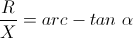
                      In any intermediate angle between quadrantal angles of 0, 90, 180, 270, the values of Reactance and Resistance combine in a quadrantal vector relationship, this for intermediate angles in the first quadrant the relation is given as,


                      This is the Hysteretic Impedance for the first quadrant, and


                      Here, , is a Positive Impedance but now the Resistance has become an imaginary quantity. Likewise for the opposing quadrant the relation is given as,



                      Or by resolving powers of , it is


                      Here it is a negative Hysteretic Impedance. Hence Reactance and Resistance can be synthesized in Positive or Negative forms by positioning the Angle of Hysteresis, .

                      BK DE N6KPH
                      SUPPORT ERIC DOLLARD'S WORK AT EPD LABORATORIES, INC.

                      Purchase Eric Dollard's Books & Videos: Eric Dollard Books & Videos
                      Donate by Paypal: Donate to EPD Laboratories

                      Comment


                      • #71
                        Thank you Eric,

                        As you know, I have studied your works for a couple of years now trying to gain insight and it has not been until recently that my mind has began to really connect the puzzle pieces of your "Symbolic Representation of the Generalized Electric Wave in Time" book. I have to say that I am truly impressed with your ability to organize electrical phenomena symbolically. The series of writings that you have been putting into the public domain has been the most articulate, well-written information that I have ever read regarding electrical phenomena. I believe your transmissions to be priceless.

                        Just a reminder to all, Eric is doing all of this in hopes that he will receive some type of compensation for all of his efforts. If you feel that you are taking away anything of value from his transmissions, please donate what you can. I can assure you that he is not living a life of luxury.


                        Dave
                        Last edited by Web000x; 07-30-2012, 11:29 PM.

                        Comment


                        • #72
                          The Law of Electro Magnetic Induction, Eleven.

                          (1) Magnetic materials such as Iron exhibit internal parameter variations during a Magnetic cycle of Induction. These can be divided into two distinct phenomena, Saturation and Hysteresis. It has become commonplace to consider the two as a single phenomena, but this leads to misleading concepts. Saturation and Hysteresis must be analyzed separately.


                          Saturation gives rise to a Non-Linear loadline. The path taken by a point on this curve thru the A.C. cycle follows the same path up the curve as down the curve. This curve defines a single path. Also, here in the Iron, the Saturation curve is Symmetrical, both positive and negative values give the same curvature. The Non-Linearity of the Saturation curve gives rise to Dis-Proportion between cause and effect. This in turn distorts the wave into a non-sinusoidal form. A series of odd ordered harmonics is produced by this non-linear distortion. This is an Amplitude Distortion of the A.C. wave.

                          Hysteresis gives rise to an Elliptical loadline. A point on this curve does not follow the same path up the curve, as that path down the curve. Each path is on one or the other side of the elliptical curve. This path is now a loop. The elliptical load line is ultimately derived from a linear curve as a side view of a rotating circle. Hence the distortion produced is not an amplitude distortion as normally considered. In the elliptical curve the distortion is not the result of a dis-proportionate relation between cause and effect as with the Saturation, rather it is that cause and effect have become separated in a time loop. Thereby Hysteresis gives rise to a Phase Distortion in the A.C. wave.

                          Parameter variation of Inductance by external means, thru rotation or controlled saturation, can be utilized to develop synthesized Saturation and Hysteresis curves unique from those of the Iron itself. The practical knowledge in this realm is very limited. Experimentation is required here.

                          The principle apparatus utilizing parameter variation are the developments of Ernst Alexanderson, the Variable Induction Alternator


                          and the Magnetic Amplifier.


                          The alternator is a complex machine but the Mag-Amp is a quite simple device. The Mag-Amp is where to begin the study of parameter variation.

                          The utilization of the Mag-Amp as a parameter variation device is somewhat different than its use as an amplifier. As an amplifier it serves as a variable Impedance, consumingadvanced in phase, but still rotating in synchronism with the wave. With increasing excitation the machine begins to draw a leading Current from the power line, the greater the excitation, the greater the current taken by the machine from the line. Since these Currents are reactive no Energy is expended in maintaining them. Here the Synchronous Machine is exhibiting the characteristics of and Electro-Static Condenser and in this manner of operation it is called a Synchronous Condenser.

                          Inversely, reducing the Field Current below that required to maintain a neutral condition, the rotor falls behind the A.C. wave of the stator, this to a position retarded in phase while rotating with the A.C. wave. The less the excitation, the more the rotor lags behind the stator. With decreasing excitation the Machine draws a lagging Current from the power line, the less the excitation, the more Current is drawn. Here the machine is exhibiting the characteristics of a Reactance Coil. This can be called a Synchronous Reactor.

                          In this manner the Synchronous Machine is operating as a two terminal Reactance Arm. There is no connection to the rotating shaft. The Machine can synthesize an actual Inductor or Condenser. Operating in this manner the machine can create a substantial reactive power flow, this flow controlled by the D.C. excitation of the machine. This Controlled Reactance is used at the end of long distant power lines in order to regulate the voltage and phase at lines end.

                          As a reactance arm the two terminals (per phase) serve as input and serve as output. There is only one power line. The Energy flows into the machine during one part of the Cycle, and Energy flows out of the machine during another part of the Cycle. Here input and output are separated in Time rather than space. The Energy is caught in a Hysteresis Loop.

                          It is important to note here that this machine is operating as a Synthesizer
                          SUPPORT ERIC DOLLARD'S WORK AT EPD LABORATORIES, INC.

                          Purchase Eric Dollard's Books & Videos: Eric Dollard Books & Videos
                          Donate by Paypal: Donate to EPD Laboratories

                          Comment


                          • #73
                            Secondary and extra coil tuning

                            Hi dR-Green: Thank you for the help with the set up. With the 5.5 mm wire spacing I done 3 tests with can at 16 cm, 8 cm and 1 cm above secondary. The lower the can was the higher the frequency reading (although not by much). While keeping the can on the axis of the secondary I set the frequency to 1,188 Kc (my target frequency) and kept raising the condenser ring until at 64 mm above the the top ring I got max meter reading. I then took the can and measured the meter response in the radial direction from the top ring which was at approximately 4 cm from the top ring. Next I placed my old extra coil on top of the secondary and connected per your diagram. This extra coil will be redone with about #13 AWG wire, currently the wire is #25 AWG and 124.25 turns with a tap at 49.5 turns.
                            When the can held radial to the top ring I get two resonant peaks, the 1st @ 724 Kc and the 2nd @ 1,267.3 Kc. If I connect the extra to the top of secondary via the top ring at the 49.5 turn tap point then the first resonant peak is @925.5 Kc and the 2nd @ 1,186 Kc. During these measurements I left the condenser ring at 64 mm above the top ring. I think my results are good but comments are welcome. Next I will rewind the secondary with 4 mm wire spacing to see if I can increase the secondary's response frequency. If I see an increase then I will rewind for 3.5 mm wire spacing if not then I will do a final rewind at 5 mm wire spacing.

                            Comment


                            • #74
                              Originally posted by Nhopa View Post
                              When the can held radial to the top ring I get two resonant peaks, the 1st @ 724 Kc and the 2nd @ 1,267.3 Kc.
                              Very good What you could also do there now is adjust the condenser rings to make it resonant at 1188 kc and then see what frequency the secondary is tuned to, just for future reference.

                              4cm pickup distance sounds a bit close. Yours might not be as sensitive as mine at a higher frequency, but be careful you're not bringing the frequency down by having it too close.

                              I think 4mm spacing will give a lower frequency due to the extra capacitance, also the height to width ratio would be less so that would also contribute to it being lower? Is any of them 62%? It will be good data to have anyway
                              http://www.teslascientific.com/

                              "Knowledge is cosmic. It does not evolve or unfold in man. Man unfolds to an awareness of it. He gradually discovers it." - Walter Russell

                              "Once men died for Truth, but now Truth dies at the hands of men." - Manly P. Hall

                              Comment


                              • #75
                                Reproduction 1989 Dollard Demonstration Device (DDD)

                                Dear T-Rex,

                                I have built a first version "Wagon Wheel" Tesla pancake coil as close as I can to what appears in the vintage video. Right now I'm still doing shake down tests and collecting working instrumentation. (I didn't realize that I have 3 signal generators that don't work). So, all the following measurements are tentative.

                                You mentioned that the primary and secondary were tunned to resonate at harmonic frequencies.

                                Right now my primary rings at 5.4 MHz (using 7350 pF from a vacuum variable capacitor with 1.4 uH in the copper strip primary). The secondary rings at 2.7 MHz. with a measured inductance of 217 uH in the open circuit mode with a 5-pie section 17 mH RF loading inductor in series. Is this the intent of this system to have the secondary oscillate at a lower harmonic than the primary?

                                This seems to be a 1:2 harmonic ratio. Is it deseriable to shoot for a 1:3 relationship to take advantage of harmonic voltage addition?

                                If this device is to operate in transmission line mode just where should the minimums and maximums take place?

                                The NE-34 lamps lights up nicely, but I don't have any observable action on my appliance lamp. Right now I'm working at the lowest Diathermy input current setting.

                                The 1B22 arc tubes display purple streamers inside.

                                Right now I'm using the Diathermy output between the "Low voltage" terminal and the "High voltage terminal". I could use the "Indifferent" terminal as my low side, but I can't tell from the video if this is what you were doing or not.

                                I noticed that you didn't use the Tesla secondary knob. I was wondering, even though it is not providing a current output it is still in the circuit like a parametric tank element. Was the frequency of this Tesla secondary an important frequency component in the tuning of your transformer?

                                Spokane1

                                Comment

                                Working...
                                X