-
-
Is the wire # in awg? Not seen those numbers flying around here. Are you building a ssg? if so go to radio shack and pick up the mag wire they have. wind the green 26 awg and red 30 awg, this should give you the turns you will need. 200 some odd for your power and around 600 for your trigger. This should also help with the heating of your coil. The rest of your parts sound spot on. Hope this helps.Comment
-
multi coils setup
Thanks Blackchisel97
Ok, using the diagram that's been floating around the forum, I've wound a single slave coil with three layers of awg 23, about 40 ft each layer. I am using a transiter for each as well, but using the main cuircut to trigger the slave coil. Each layer has a kill switch in line with the slave resistor (47 ohms). The system starts fine and as I flip the switches the pitch goes up like if I was adjusting the pot. However, the rotor slows and the multi meter shows a voltage decrease. It was my impression that the voltage spikes would go up not down. Not sure about the speed. Weather is goes up or down is unknown to me, but that would help if I knew, that way I can gauge for myself. I've taken care to set the magnets at a 90 degree angle so they are center at both coils per each pass. The magnets are not neos. The prime coil has a core where the slave is an air core, not sure if that has any bearing. Thanks for any help you can give.
Robert.Comment
-
Comment
-
Glade to hear it. Make a youtube video and post it. I'd love to see your setup.Comment
-
multi coils setup
Jetijs, here is the picture of the setup I'm implamenting.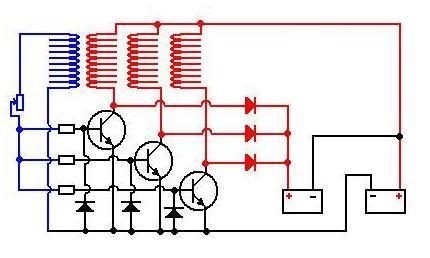
Comment
-
Why did you decide to separate trigger coil from power coils? I have build this but all coils are wound together on same spool. Ceramic magnets are too weak to work with air core. I would fit your slave with core as well.Originally posted by eastcoasttinker View Post
Vtech'Get it all on record now - get the films - get the witnesses -because somewhere down the road of history some bastard will get up and say that this never happened'
General D.Eisenhower
http://www.nvtronics.orgComment
-
Hi Blackchisel97,
The coil with the iron core is a bifiler bedini coil (standard SSG). The 2nd is the slave. It has the three layers of awg 23. I had a hunch the slave might need a core. Wasn't sure if the iron would slow the rotor down. Is that my problem then? No core in the salve? And if I add it, I should see better charging?Comment
-
Nunoarao,
Just watched your youtube video. It's looks to me that your voltage spikes are bearly enough for charging. The meter shows about 15 volts. In my experience 20 volts is where good charging starts.
Suggestions
1. place a neon accross your emitter and collector. When your charge batt is not connected you can see if you're getting at least 90 AC. If it doesn't light, you need to increase resistance or place a relay coil in the trigger. (My SSG will light a neon starting at 6 v. The neon is a good gauge for output,)
2. I talked about the relay. Use only the coil in the relay. I have a SSG that wouldn't light with low voltage on the prime batt, but would when one is placed in the trigger of the SSG.
3. Try putting in a 1 - 5 k pot in the trigger as well. Didn't see it in your video. Again I have a mag lev that is fussy. I have to tune the pot just right or it won't run. However, when I do tune it right, it takes off, sometime to fast.
4. Here's another thing I found. John Beddini shows a light bulb in his cuircut. Most people omit it. I did too, for a while. I started to play around with them and it did wonders with a ssg I wanted to run on solar power. Without the bulb the engergize spun slow. Added a bulb however and the speeds increased (It is said that the bulb helps tune the batt to the coil. Look into impedance).
5. In your video I saw your magnets fixed to the rotor by what looked like wire. Is that true? If so make sure a magnet doesn't stike to them. If they do, then that might be a reason why your rotor is slow. The metal might be causing drag.
6. I've have from time to time, damaged my transister. Funny thing was it spun the rotor, but not fast enough to do charging. I now it's a pain to replace one, but that might be the problem too.
Hope this helps
Robert.Comment
-
Dead Batt.
Got a question on saving Nicad's or (cordless drill batt.) I got one here and trying to bring it back to life. It was given to me by a friend, so I know nothing about it or what happened to it. It reads 0 on the meter, even after charging for 24 hours. One time it read .001 mv for about three seconds, then when to 0. Can this batt. be saved? Meaning, is there a method I should use to condition it. Say charge for 24 hours then let it rest for an hour then continue the charging for another 24 hours? And if so, what should I expect? Just wanted to know if anyone else as run across this issue and knows anything about it.
Thanks.Comment
-
Hello all, this is my first post in this thread. I've build a little monopole energizer using a skateboard wheel with 4 ceramic magnets. I run it from a rechargable 9v 200mAh battery and charging an identical one. I haven't manage to run it for more than 30 minutes before the drive battery drains, during which time the charge battery would have charged at 20% in the best case scenario. I know that John Bedini insists on replicating his designs exactly at first before making any changes, which I find reasonable. Since my energizer is a lot different from the original and I also didn't manage to find the sweet spot yet I'll reserve my jugdement on this one. But then I decided to replicate the school girl science fair motor which i could built quite close to the specifications. I wanted to test the claim that it can run for 5 days on a 9v battery. Also in the energizer we have the neon bulb so the transistor doesn't blow up from the flyback voltage spikes in case the charge battery wasn't connected. I was curious to see if it would be somehow protected in this design. I got my info from this page: Bedini Motor test. I used a bifilar coil with welding rods core and 0.45mm and 0.6mm wires at about 600 turns. The transistor was a 2n3055, the diode a 1n4148 and I used a 1k potensiometer set somewhere between 650-700 Ohms. I run my setup from a brand new 9v 200mAh battery. In about 5 minutes the transistor blew up. I managed to take current measurement before that. I measured 210mA free running and it droped to 150mA when loaded (approached another coil) .When I tried a 10 Ohm resistor at first the current was off the roof. This was nowhere near the 22mA claimed. So my question is this: has anyone managed to get this running for days like the school girl is supposed to have done? Also how would this be possible without the transistor failing?Comment
-
How To Fix a Bedini SG circuit
you need a amp meter in you input your chip could be damaged I have a small charger I use to charge nicad batteries the base voltage has a 100ohm and 100-600 adjustable pot but my chips are nte36 you need to be sure you have a base Resistance 50-100 ohms 10 ohm seems low. I think in the early days I never went below a 20ohms 100ohms works for my set up may this will helpOriginally posted by harctan View Post
How To Fix a Bedini SG circuit
 Tecknomancer
Zeropointfuel.comComment
-
Coper wire
Hi, Can anyone tell me about the material for wound coil spool ?
Should it be plastic material?
Or can I use it with metal material?
Regards,
KjpComment
-
Coil Bobbin
Kjp,Originally posted by kajironpu View Post
Keep it non-metallic. Most metals affect magnetic flux, even aluminum. I have experimented with many coil geomitries, so I build my own bobbins. I just use old cores from wax paper, aluminum foil, paper towels, whatever you find around the kitchen and then plexi on the ends. Glue them on with super glue. I have also use craft dowels for the cores of my bobins.
RandyComment

This forum is preserved as a permanent archive. The community continues at eMedia Press.
- If this is your first visit, be sure to check out the FAQ by clicking the link above. You may have to register before you can post: click the register link above to proceed. To start viewing messages, select the forum that you want to visit from the selection below.

 Tweet
Tweet

Comment