This forum is preserved as a permanent archive. The community continues at eMedia Press.

Announcement

Collapse
No announcement yet.

Wood Gasification

Collapse
X
 
  • Filter
  • Time
  • Show
Clear All
new posts

  • #46
    Ok... I have been in the dog house for a week now and it is time to stop working and take a break... so... here is the last little bit you need:

    Heating Water With HHO Hydroxy Hydrogen Part 1 of 2 from HHOG Labs - YouTube

    Heating Water With HHO Hydroxy Hydrogen Part 2 of 2 from HHOG Labs - YouTube

    So, no need for steam injectors, no need to vent the boiler to atmosphere to refill... just heat it in a way that the waste product is water and refills your boiler... close the loop

    That's it, that's all the information you need, so go forth and be happy and free!


    Rob Mason

    Comment


    • #47
      Pulsometer Theory of Operation Part 1

      562 Forms of the Steam Engine

      307

      The Pulsometer.

      Halls pulsometer is a peculiar pumping engine without cylinder or piston, which may be regarded as a modern representative of the engine of Savery. The sectional view fig 261, shows it's principal parts. There are two chambers, A, A', narrowing towards the top, where the steam pipe B enters. A ball valve C allows steam to pass into one of the chambers and closes the other. Steam entering (say) the right hand chamber forces water out of it past the clack valve V into a delivery passage D, which is connected with an air vessel. When the water level in A sinks so far that steam begins to blow through the delivery passage, the water and steam are disturbed and so brought into intimate contact, the steam in A is condensed and a partial vacuum is formed. This causes the ball valve C to rock over and close the top of A, while water rises from the suction pipe E to fill that chamber. At the same time steam begins to enter the other chamber A', discharging water from it, and the same series of actions is repeated in either chamber alternately.

      While the water is being driven out there is comparatively little condensation of steam, partly because the shape of the vessel does not promote the formation of eddies, and partly because there is a cushion of air between the steam and the water. Near the top of each chamber is a small air valve opening inwards, which allows a little air to enter each time a vacuum is formed. When any steam is condensed, the air mixed with it remains on the cold surface and forms a non conducting layer. Further, when the surface of the water has become hot the heat travels very slowly downwards so long as the surface remains undisturbed. The pulsometer of course cannot claim high efficiency as a thermodynamic engine, but it's suitability for situations where other steam pumps cannot be used, and the extreme simplicity of it's working parts, make it valuable in certain cases. Trials of it's performance have shown that under favourable conditions a pulsometer may use no more than 150lb of steam per effective horse power hour. This consumption, large as it is when judged by the standard of an efficient large engine using steam expansively, does not compare very unfavourably with that of small non rotative steam pumps.

      1 Proc. Inst. Mech. Eng. 1893, p456

      The Steam-Engine and Other Heat-Engines - Google Books

      This is google books, when they realise people want to read this they will try and make you pay for it, so I have typed it out. Ignore the references to letters designating parts of the system, as the diagram is not there, but that does not matter because I will provide a better one in a few minutes.

      This has valuable insights into the theory of operation of the Pulsometer, which when combined with Part 2 about to follow tells you everything you need to know to replicate the design.

      RM

      Comment


      • #48
        Pulsometer Theory of Operation Part 2

        This section is from the book "Cassell's Cyclopaedia Of Mechanics", by Paul N. Hasluck. Also available from Amazon: Cassell's Cyclopaedia Of Mechanics.

        The Pulsometer

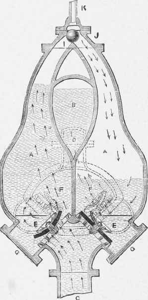
        The illustration shows a sectional elevation of a pulsometer, which is an appliance for raising water by the alternate pressure and condensation of steam.

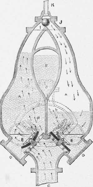
        To describe the parts, K is a pipe from a boiler containing steam under pressure. The gunmetal spherical valve is free to move and to alternately cover the necks I and J. The latter form the upper parts of the chambers A A, into which water passes through the valves E E from the suction pipe F. G G are doors for access to the valves E E for repairs or other attention.

        Near the bottom ends of A A are side outlets, as shown by the dotted circles, covered by the valves V P, also shown by dotted lines, opening into a chamber with which are connected the air vessel K (should be B) and the outlet branch D, to which the delivery pipe is attached. The action is as follows.

        The pump is first charged with water through plugholes provided for the purpose, and then steam is turned on at K. This presses on the water on the right hand chamber A (which is not covered by the spherical valve), and forces it, as shown by the arrows, through the right-hand valve F and up the delivery pipe.

        The steam in the right-hand chamber A then condenses, and causes the spherical valve to roll over and cover the neck J, and also creates a vacuum, which is again filled with water through the right-hand valve E from the suction pipe C. When the valve has rolled over J, the steam passes through the open neck I and presses on the water in the left-hand chamber A, forcing it through the dotted left-hand valve F into the delivery chamber.

        When the left-hand chamber A is nearly empty, the valve is again pulled back by the condensation of the steam in the chamber, which again fills with water during the time the other chamber is being emptied, and these actions continue as long as steam under efficient pressure is supplied.

        As water will not rise in a vacuum beyond a certain height, a pulsometer should not be fixed more than about loft. or 20 ft. above the water to be raised, although theoretically the limit is a little more than 30 ft. The pump can be slung on chain s in a well or sump, so that there is very little trouble in fixing it, or lowering it when necessary for keeping within a working distance of the water.

        The height to which a pulsometer will raise water depends on the pressure of steam in the boiler, which is used in conjunction with the apparatus.

        Read more: The Pulsometer

        The central chamber that was causing everyone a headache operates as a pneumatic buffer to prevent water hammer, as in a hydraulic system. The two non return valves that allow air into the chambers (not shown on any diagrams) now make perfect sense as to the function, because of the insulating and compressible layer they form between the steam and the water, preventing instant condensation on contact and allowing the Pulsometer to function as both a vacuum and compression pump.

        With modern technology and improved design this device will become much more efficient, it reportedly produces 50 metres of head at high mass flow rates, and as we all know mass flow rate can be converted into higher pressure by use of a de laval nozzle.

        The system I have described in this thread is perfect for small scale home power generation, and if at some point in the future a heat source becomes available that does not require high levels of fuel it can simply replace the gasifier.

        Have fun

        RM

        I have highlighted in bold what I believe is an error in the description, the air vessel is denoted B on the diagram, K is the steam injection pipe.
        Attached Files
        Last edited by evolvingape; 02-21-2012, 06:22 AM.

        Comment


        • #49
          Turgo Turbine


          The Turgo turbine is an impulse water turbine designed for medium head applications. Operational Turgo Turbines achieve efficiencies of about 87%. In factory and lab tests Turgo Turbines perform with efficiencies of up to 90%.

          Developed in 1919 by Gilkes as a modification of the Pelton wheel, the Turgo has some advantages over Francis and Pelton designs for certain applications.
          First, the runner is less expensive to make than a Pelton wheel. Second, it doesn't need an airtight housing like the Francis. Third, it has higher specific speed and can handle a greater flow than the same diameter Pelton wheel, leading to reduced generator and installation cost.

          Turgos operate in a head range where the Francis and Pelton overlap. While many large Turgo installations exist, they are also popular for small hydro where low cost is very important. Like all turbines with nozzles, blockage by debris must be prevented for effective operation.

          Theory of operation

          The Turgo turbine is an impulse type turbine; water does not change pressure as it moves through the turbine blades. The water's potential energy is converted to kinetic energy with a nozzle. The high speed water jet is then directed on the turbine blades which deflect and reverse the flow. The resulting impulse spins the turbine runner, imparting energy to the turbine shaft. Water exits with very little energy. Turgo runners may have an efficiency of over 90%.

          A Turgo runner looks like a Pelton runner split in half. For the same power, the Turgo runner is one half the diameter of the Pelton runner, and so twice the specific speed. The Turgo can handle a greater water flow than the Pelton because exiting water doesn't interfere with adjacent buckets.

          The specific speed of Turgo runners is between the Francis and Pelton. Single or multiple nozzles can be used. Increasing the number of jets increases the specific speed of the runner by the square root of the number of jets (four jets yield twice the specific speed of one jet on the same turbine ).

          Renewable Components - Manufacturers of MiniWind Downwind Domestic Turbines

          These Turgo Cups are moulded in very durable Polycarbonate plastic, and are easily replaceable if they become worn or damaged.* Their design allows the user to create a wide range of wheel diameters, but we can supply a moulded plastic turgo disc of 260mm diameter (giving a jet PCD of 330mm) to match the performance of our 2200W PMG range of generators.

          The design of our turgo discs gives a very robust mounting of the cups, allowing the completed turgo wheel to be used with up to 4 jets of 30mm diameter, giving powers from a few hundred watts to over 2200W.* The flexibility of this design allows the user to match the turgo turbine's performance to the available water head and flow rate.* Each plastic turgo disc takes 24 turgo cups.

          Turgo turbines are generally more suited to lower head, higher flow rate applications than the pelton turbines, and typically your site will require a minimum head height of 10-15m to be effective.

          Custom Turgo Turbines - better than a pelton.

          3 Phase Brushless generators for MicroHydro

          EcoInnovation - Pelton Spoons and Fixings

          Comment


          • #51
            Hi iApe,

            About the heating of the water with HHO, i would suggest using a preferably tungsten plate to aim your flame at and the water above.

            Why? note: It's my opinion, no scientific claim

            In my experience i came to the conclusion the temperature of HHO flame differs with the subject touched by the flame.

            I know it sounds strange, but you can almost touch a hho flame with your skin (don't try!) but when you aim the flame at a solid material it gets much hotter.

            So heating a tungsten, or more simple steel or pottery from the outside makes it more hot as with direct heating the water with the flame inside.

            See this: Water power - YouTube
            Last edited by Cherryman; 02-21-2012, 07:47 AM.

            Comment


            • #52
              Hi Cherryman,

              Yes there are quite a few options I have been considering for a while now.

              Have a look at these links:

              Plasma Flame Theory

              Plasma Gas Flow Conversion Calculator for Metco 7MC

              Plasma spray processing - Appropedia: The sustainability wiki

              One viable option I have been thinking about pursuing is placing an air venturi on the low pressure HHO line from the bubbler. As we can see from the ionisation energies chart Nitrogen has a high energy content per volume, and as the air around us is 78% Nitrogen with about 21% Oxygen it seems a very sensible option, considering it is abundant and free.

              The other gases Argon and Helium provide more heat output, but you need to supply them so probably not the most efficient option in terms of infrastructure.

              If we look at it from the perspective of using the Hydrogen as a secondary supplemental gas, and for example split the HHO line into two output torches, with the primary gas in both lines being Nitrogen, then we may substantially increase the energy created for the same amount of HHO generation cost.

              I have also been considering using an absorber to store the heat, same principle as putting a hot rock into a fire and then dropping it into a bucket of water to boil the water. The only problem I have here is finding a material that will not melt from the plasma flame. HHO flames cut through just about everything and many years ago I tried it on everything I could find, everything melted. One possibility might be some kind of ceramic ?

              Interesting stuff anyway, HHO heating, even secondary as a gasifier does now will become much more efficient when we start using Nitrogen plasma as the main gas, because it is free!

              Air Composition

              Rob

              Just a quick note - There would be two ways of doing this:

              The first would be as I have already suggested, adding a venturi to the low pressure HHO line, which would suck in a little air, but not that much as it is reliant on the HHO gas pressure passing over the venturi to draw the air in under vacuum, but still worth trying because of it's simplicity. Then compare the results to straight HHO heating and the difference is the efficiency increase.

              The second way would be to run a pressurised air line via a Tesla turbine pump, and use the venturi to suck in small amounts of HHO constantly. The Tesla pump can be run from the Turgo turbine shaft with very little cost because the air is such a thin fluid it would not load it very heavily, and we are only looking for low feed pressures, and the infrastructure to drive the pump is already there. The amount of HHO required to generate a flame could then be determined by altering the pump speed. (probably best to run the Tesla pump off a variable motor for testing purposes, and when the correct speed is known hard wire that ratio from the main turbine shaft.

              Multiple venturis at different points on the air line would allow plenty of time for the gases to mix before reaching the torch tip. Then it's just a case of seeing what ratios you can get to reliably stay lit and testing the resultant heat output.

              Make sure you only conduct these experiments in an open container, do not go sealing it, don't want any explosions now do we

              Last edited by evolvingape; 02-21-2012, 09:36 AM.

              Comment


              • #53
                Time for a summary of the system so far...

                We have a gasifier burning a hydrocarbon fuel such as woodchips, turning potential energy into heat energy. This is our prime mover of the system and the heat generated is used to power a boiler filled with water.

                The boiler creates steam pressure because the heat energy applied to the water causes a phase change from liquid into steam, which is used to power a Pulsometer steam pump.

                The Pulsometer creates water pressure and high mass flow rates, via opposite cycles of expansive compression and partial vacuum implosion, the implosion caused by the rapid condensation of steam into liquid water. These cycles are used to power a Turgo turbine, optimised for low pressure and high mass flow rates.

                The turbine is driven by water jets and rotates about a shaft, this rotary moment turns a permanent magnet generator that creates an electrical potential. This electrical energy is our output from the system.

                The water that is exhausted from the turbine enters a reservoir. This water has been stripped of it's kinetic energy in order to turn the turbine and now has only potential energy because it is within a gravitational field.

                This static water potential is then gravity fed to our individual Kelvin generator reservoirs, which are powered by the gravitational field to drip water and induce an electrostatic potential difference of 15,000 kV approximately.

                The electrical output from the PMA is used to power a DC parallel series dry cell bank resistor. The HHO produced is pumped under it's own low pressure to our nozzle ring, which is submersed within an open water tank which surrounds our boiler in a secondary sleeve.

                The nozzle ring consists of two sleeved tubes. The inner tube carries low pressure HHO, Hydrogen and Oxygen in a stoichiometric ratio. The outer ring carries low pressure air, 78% Nitrogen, 21% Oxygen, 1% Argon, + trace gas elements.

                The two pipes carry opposite electrical potentials at the tips. This potential difference is supplied by a capacitor bank, which is in turn charged by the electrostatic potential difference of the Kelvin generators. A control circuit will sense the charge status of each individual capacitor storing energy from the Kelvin generators, and trigger capacitive discharge as appropriate in a timed pulse cycle.

                The high voltage capacitive discharge will cause dielectric breakdown of the air and electrostatic discharge will result, creating a conductive path and the generation of a rapid increase in the number of free electrons and ions in the air. The spark will also cause the Hydrogen and Oxygen, supplied separately to the same location to detonate.

                A high temperature plasma will result, rapidly heating the localised area, and transferring that heat energy to water that the plasma detonation is submersed in.

                This water will then heat the steam boiler. Should the resultant energy released by the plasma detonations equal the energy being supplied by the gasifier, the gasifier can be turned off by closing the air intake, and the process will become self sustaining, at unity.

                This system exploits the many different possibilities that exist for energy conversion, phase changes of matter, pressure, velocity, mass flow, and in general it is based on potential difference, the fundamental principle that drives our universe.

                One particularly elegant example of this principle is the choice of the Turgo turbine as the optimum because it requires low pressure but high mass flow rate. The Kelvin generators require gravitational pressure and low mass flow rate, so the potential difference between the high mass flow rate of the turbine exhaust and the low mass flow rate demand of the Kelvin generators can be fully exploited by multiplying the Kelvin generators until balance is achieved. The pressure required by the Kelvin generators is supplied by the gravitational field, which converts potential energy into kinetic energy.

                As the main water reservoir supplying the Pulsometer must be replenished from time to time, smart circuitry with float sensors will trigger a release from the Kelvin generator exhaust reservoirs and the water will gravity flow back to the main reservoir, where the opposite charges will neutralise, and the cycle continues.

                This entire process rests on one simple question... Will the plasma be able to match the gasifier for heat output ? If the answer is yes then unity at minimum is achieved. If the answer is no then the gasifiers will continue to supply heat to make up the difference.

                It sure is going to be fun finding out though... isn't it ?


                RM

                Comment


                • #54
                  HHO High Voltage Plasma Torch Detonation Heating

                  Let's have some fun!

                  HHO flame / ionized spark gap 2 - YouTube

                  plasma flame - YouTube

                  Plasma Electrolysis with tap water - YouTube

                  Pretty cool stuff eh!

                  Twin HHO and compressed air feeds to the same nozzle, with a 15,000 kV DC spark will create an ionised plasma and will also detonate Hydrogen. This Plasma Detonation Torch being submerged under water will transfer it's energy as heat and shock waves and the water will boil.

                  The positive gas supply pressure will create a protective shield to prevent water extuingishing the flame as demonstrated by hhoglabs very nicely!

                  The high voltage capacitor discharge event required to generate both plasma and ignition conditions is supplied by the gravitational field at zero cost to you.

                  The prime mover to stimulate a reaction in the gas composition is free as long as the water, which the gravitational field requires to work on, has a potential difference head. This is supplied continuously by the turbine, which being at a higher level relative to the centre of the Earth, will create a natural head.

                  The cost in moving water against gravity to balance the system, and to rotate the turbine to create the gas, is provided by the Pulsometer which is powered by steam. The generation of steam requires heat and so the input energy is now the same form as the output energy. This allows potential for a closed loop system.

                  The cost of producing the gas for the torch is in HHO generation and air compression (possible venturi option for the air, if there is sufficient HHO pressure to cause a vacuum, a HHO pump would be useful).

                  You build the infrastructure of the system in such a way that all of the necessary energy change conversions required to generate the raw materials for the reaction, are provided for, and the prime mover is a single source, heat.

                  The catalyst for the fluid phase change reaction is primarily gravitational, with conversion from potential to kinetic energy. The resultant effects on a water droplet, creating a static electrical field, that creates an electrical discharge event, that creates a plasma event, are all free to you.

                  This is how you can use gravity as a catalyst to create a plasma reaction, if the environment is right.

                  Fun isn't it, and you have a large selection of components, processes and systems to choose from... what can you make ?

                  Rob
                  Last edited by evolvingape; 02-22-2012, 08:16 AM.

                  Comment


                  • #55
                    To give you an idea of the sort of things you can design with all these concepts here are some examples:

                    Take this principle:

                    Plasma Electrolysis with tap water - YouTube

                    Use it in this device:

                    PLASMICS

                    Generate an energetic fluid impulse and fire it into this device:

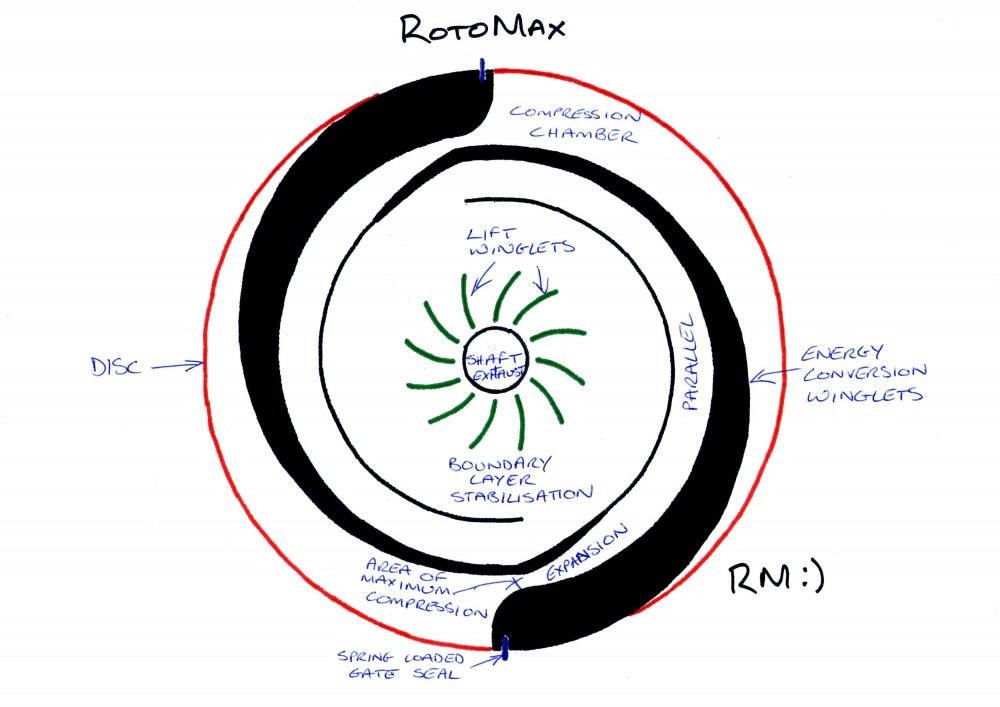
                    RotoMax Rotary Engine... Tesla - Wankel - Mason HHO Hybrid

                    And this principle observed here:

                    Soda Can Crusher - Cool Science Experiment - YouTube

                    and here:

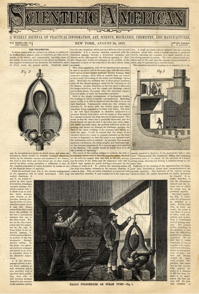
                    The Pulsometer

                    will happen... won't it ?

                    RM
                    Attached Files

                    Comment


                    • #56


                      inertial (or transient) cavitation and non-inertial cavitation.

                      Inertial cavitation is the process where a void or bubble in a liquid rapidly collapses, producing a shock wave. Inertial cavitation occurs in nature in the strikes of mantis shrimps and pistol shrimps, as well as in the vascular tissues of plants. In man-made objects, it can occur in control valves, pumps, propellers and impellers.

                      Non inertial cavitation is the process in which a bubble in a fluid is forced to oscillate in size or shape due to some form of energy input, such as an acoustic field. Such cavitation is often employed in ultrasonic cleaning baths and can also be observed in pumps, propellers, etc.

                      Since the shock waves formed by cavitation are strong enough to significantly damage moving parts, cavitation is usually an undesirable phenomenon. It is specifically avoided in the design of machines such as turbines or propellers, and eliminating cavitation is a major field in the study of fluid dynamics.

                      Hydrodynamic cavitation describes the process of vaporisation, bubble generation and bubble implosion which occurs in a flowing liquid as a result of a decrease and subsequent increase in pressure. Cavitation will only occur if the pressure declines to some point below the saturated vapour pressure of the liquid. In pipe systems, cavitation typically occurs either as the result of an increase in the kinetic energy (through an area constriction) or an increase in the pipe elevation.

                      Hydrodynamic cavitation can be produced by passing a liquid through a constricted channel at a specific velocity or by mechanical rotation through a liquid. In the case of the constricted channel and based on the specific (or unique) geometry of the system, the combination of pressure and kinetic energy can be created when the hydrodynamic cavitation cavern downstream of the local constriction generating high energy cavitation bubbles.

                      The process of bubble generation, subsequent growth and collapse of the cavitation bubbles results in very high energy densities, resulting in very high temperatures and pressures at the surface of the bubbles for a very short time. The overall liquid medium environment, therefore, remains at ambient conditions. When uncontrolled, cavitation is damaging; however, by controlling the flow of the cavitation the power is harnessed and non-destructive. Controlled cavitation can be used to enhance chemical reactions or propagate certain unexpected reactions because free radicals are generated in the process due to disassociation of vapours trapped in the cavitating bubbles.

                      Orifices and venturi are reported to be widely used for generating cavitation. A venturi, because of its smooth converging and diverging sections, has an inherent advantage, over the orifice, that it can generate a higher velocity at the throat for a given pressure drop across it. On the other hand, an orifice has an advantage that it can accommodate more number of holes (larger perimeter of holes) in a given cross sectional area of the pipe.
                      Hydrodynamic cavitation can improve industrial processes. For instance, cavitated corn slurry show higher yields in ethanol production compared to uncavitated corn slurry in dry milling facilities.

                      This is also used in the mineralization of bio-refractory compounds which otherwise would need extremely high temperature and pressure conditions since free radicals are generated in the process due to the dissociation of vapours trapped in the cavitating bubbles, which results in either the intensification of the chemical reaction or may even result in the propagation of certain reactions not possible under otherwise ambient conditions.

                      Pumps and propellers

                      Major places where cavitation occurs are in pumps, on propellers, or at restrictions in a flowing liquid.

                      As an impeller's (in a pump) or propeller's (as in the case of a ship or submarine) blades move through a fluid, low-pressure areas are formed as the fluid accelerates around and moves past the blades. The faster the blades move, the lower the pressure around it can become. As it reaches vapour pressure, the fluid vaporizes and forms small bubbles of gas. This is cavitation. [B]When the bubbles collapse later, they typically cause very strong local shock waves in the fluid, which may be audible and may even damage the blades[/B].

                      Cavitation in pumps may occur in two different forms:

                      Suction cavitation occurs when the pump suction is under a low-pressure/high-vacuum condition where the liquid turns into a vapour at the eye of the pump impeller. This vapour is carried over to the discharge side of the pump, where it no longer sees vacuum and is compressed back into a liquid by the discharge pressure.

                      This imploding action occurs violently and attacks the face of the impeller. An impeller that has been operating under a suction cavitation condition can have large chunks of material removed from its face or very small bits of material removed, causing the impeller to look spongelike. Both cases will cause premature failure of the pump, often due to bearing failure. Suction cavitation is often identified by a sound like gravel or marbles in the pump casing.

                      In automotive applications, a clogged filter in a hydraulic system (power steering, power brakes) can cause suction cavitation making a noise that rises and falls in synch with engine RPM. It is fairly often a high pitched whine, like set of nylon gears not quite meshing correctly.

                      Discharge cavitation occurs when the pump discharge pressure is extremely high, normally occurring in a pump that is running at less than 10% of its best efficiency point. The high discharge pressure causes the majority of the fluid to circulate inside the pump instead of being allowed to flow out the discharge.

                      As the liquid flows around the impeller, it must pass through the small clearance between the impeller and the pump housing at extremely high velocity. This velocity causes a vacuum to develop at the housing wall (similar to what occurs in a venturi), which turns the liquid into a vapor.

                      A pump that has been operating under these conditions shows premature wear of the impeller vane tips and the pump housing. In addition, due to the high pressure conditions, premature failure of the pump's mechanical seal and bearings can be expected. Under extreme conditions, this can break the impeller shaft.

                      RM

                      Comment


                      • #57
                        Innovative Hydrodynamic Cavitation Technologies from Arisdyne

                        Hydrodynamic Cavitation can occur in any turbulent fluid. The turbulence produces an area of greatly reduced fluid pressure. The fluid vaporizes due to the low pressure, forming a cavity. At the edges of the cavity, small amounts of vapor break off. These form smaller cavities 100 nm to 3 mm in diameter. The smaller cavities implode under the high pressure surrounding them. This process of formation and collapse is called cavitation.

                        The implosion takes place during the cavitation process in milliseconds, releasing tremendous energy in the form of shockwaves. The power of these waves generated by the cavitation process disrupts anything in their path. Whether the waves are destructive or productive depends on Arisdyne's process control.

                        How does hydrodynamic cavitation differ from ultrasonic cavitation?

                        Ultrasonic cavitation is dependent on a source of vibrations. This makes them difficult or impossible to scale up and often creates "hot spots"controlled cavitationControlled Flow CavitationShockwaves resulting from the implosions impact the surrounding process fluid. Tiny droplets or particles result producing high-quality emulsions and dispersions.

                        Innovative Hydrodynamic Cavitation Technologies from Arisdyne

                        And a video cool... hmmm... those shapes look familiar... where have I seen them before ? what do they do ?


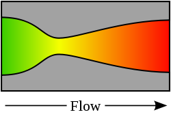
                        A de Laval nozzle (or convergent-divergent nozzle, CD nozzle or con-di nozzle) is a tube that is pinched in the middle, making a carefully balanced, asymmetric hourglass-shape. It is used to accelerate a hot, pressurized gas passing through it to a supersonic speed, and upon expansion, to shape the exhaust flow so that the heat energy propelling the flow is maximally converted into directed kinetic energy.

                        Because of this, the nozzle is widely used in some types of steam turbines, and is an essential part of the modern rocket engine. It also sees use in supersonic jet engines.

                        Similar flow properties have been applied to jet streams within astrophysics.


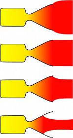
                        Nozzles can be (top to bottom):

                        Underexpanded
                        Ambient
                        Overexpanded
                        Grossly overexpanded


                        If under or overexpanded then loss of efficiency occurs. Grossly overexpanded nozzles have improved efficiency, but the exhaust jet is unstable.


                        A jet is an efflux of fluid that is projected into a surrounding medium, usually from some kind of a nozzle, aperture or orifice. Jets can travel long distances without dissipating. In the Earth's atmosphere there exist jet streams that travel thousands of miles.

                        Jet fluid has higher momentum compared to the surrounding fluid medium.In the case where the surrounding medium is assumed to be made up of the same fluid as the jet and this fluid has a viscosity then the surrounding fluid near the jet is assumed to be carried along with the jet by a process called entrainment.


                        Some animals, notably cephalopods use a jet to propel themselves in water. Similarly, a jet engine as it name suggests, emits a jet used to propel rockets, aircraft, jetboats, and submarines.


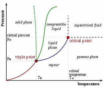
                        A supercritical fluid is any substance at a temperature and pressure above its critical point
                        , where distinct liquid and gas phases do not exist. It can effuse through solids like a gas, and dissolve materials like a liquid. In addition, close to the critical point, small changes in pressure or temperature result in large changes in density, allowing many properties of a supercritical fluid to be "fine-tuned".

                        Supercritical fluids are suitable as a substitute for organic solvents in a range of industrial and laboratory processes. Carbon dioxide and water are the most commonly used supercritical fluids, being used for decaffeination and power generation, respectively.

                        Water Steam - Critical Point

                        When water and steam reach the level of absolute pressure 3206.2 psia (221.2 bar) and a corresponding saturation temperature 705.40oF (374.15oC), the vapor and liquid are indistinguishable.
                        This level is called the Critical Point.

                        At the critical point there is no change of state when pressure is increased or if heat is added. At the critical point the water and steam can't be distinguished, and there is no point referring to water or steam.

                        For states above the critical point the steam is supercritical. Supercritical is not the same as superheated - which is saturated steam at lower pressures and temperatures heated above the saturation temperature.

                        Water physics


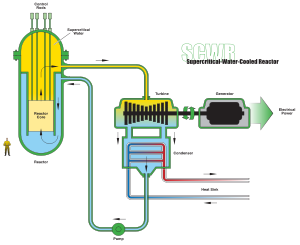
                        The supercritical water reactor (SCWR) is a Generation IV reactor concept that uses supercritical water (referring to the critical point of water, not the critical mass of the nuclear fuel) as the working fluid. SCWRs resemble light water reactors (LWRs) but operating at higher pressure and temperature, with a direct once-through cycle like a boiling water reactor (BWR), and the water always in a single, fluid state like the pressurized water reactor (PWR). The BWR, PWR and the supercritical boiler are all proven technologies[clarification needed]. The SCWR is a promising advanced nuclear system because of its high thermal efficiency (~45% vs. ~33% for current LWRs) and simpler design, and is being investigated by 32 organizations in 13 countries.

                        The PRotoMax on the other hand is a Generation I reactor that operates via controlled plasma ionisation and hydrogen detonation events in an environment with sub and supersonic fluids, jet's and mediums, while undergoing controlled expansion and implosion phenomena in an environment that is experiencing standing shock waves due to controlled cavitation of the jet stream.

                        The PRotoMax and related technologies are currently the focus of a small but talented community of open source energy researchers spread across the globe. The PRotoMax technology's are not, and never will be, subjected to patent restrictions by the inventor.


                        Water achieves supercritical point at 374oC, 647.096 K and 217.7 atm, 22060 kPa.

                        These temperature and pressure limits are heavily exceeded in a cavitation event. An event which is itself on it's way somewhere because it is occurring in a fluid that possesses inertial momentum and angular velocity, while undergoing rapid positive and negative acceleration, and experiencing extremes of pressure and vacuum, expansion and implosion events.

                        What is going to happen to the water, the fluid medium of immersion ?

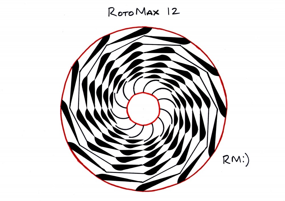
                        And the good thing about the Plasma RotoMax is... the housing is the rotor...

                        RM
                        Attached Files
                        Last edited by evolvingape; 02-22-2012, 01:44 PM.

                        Comment


                        • #58
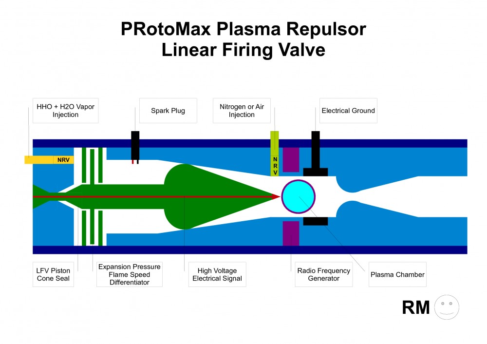
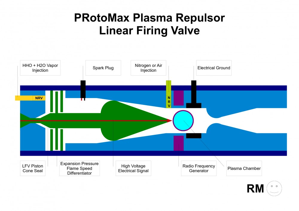
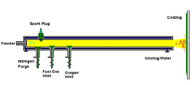
                          Compare the PRotoMax Plasma Repulsor Linear Firing Valve with the Plasma Detonation Spray Process.

                          See the identical function of water cooled barrels and Nitrogen purge cycle in both devices ?

                          There are additional processes occurring due to hydrogen detonation waves and the ionisation of air.

                          What processes will occur with a staggered timed injection of high pressure low temperature water jets, hot ionised plasma supersonic jet streams, and ambient temperature high pressure air jets, into the rotor ?

                          Which fluids are compressible and which are non-compressible ? Do these properties change with temperature ?

                          Map the expansion and compression phases for each fluid, including velocity, pressure and temperature variables, through time.

                          What is happening ?

                          RM
                          Attached Files
                          Last edited by evolvingape; 02-22-2012, 02:24 PM.

                          Comment


                          • #59


                            In thermodynamics and fluid mechanics, compressibility is a measure of the relative volume change of a fluid or solid as a response to a pressure (or mean stress) change.

                            Aeronautical dynamics

                            Compressibility is an important factor in aerodynamics. At low speeds, the compressibility of air is not significant in relation to aircraft design, but as the airflow nears and exceeds the speed of sound, a host of new aerodynamic effects become important in the design of aircraft. These effects, often several of them at a time, made it very difficult for World War II era aircraft to reach speeds much beyond 800 km/h (500 mph).

                            Some of the minor effects include changes to the airflow that lead to problems in control. For instance, the P-38 Lightning with its thick high-lift wing had a particular problem in high-speed dives that led to a nose-down condition. Pilots would enter dives, and then find that they could no longer control the plane, which continued to nose over until it crashed. The problem was remedied by adding a "dive flap" beneath the wing which altered the center of pressure distribution so that the wing would not lose its lift.[4]

                            A similar problem affected some models of the Supermarine Spitfire. At high speeds the ailerons could apply more torque than the Spitfire's thin wings could handle, and the entire wing would twist in the opposite direction. This meant that the plane would roll in the direction opposite to that which the pilot intended, and led to a number of accidents. Earlier models weren't fast enough for this to be a problem, and so it wasn't noticed until later model Spitfires like the Mk.IX started to appear. This was mitigated by adding considerable torsional rigidity to the wings, and was wholly cured when the Mk.XIV was introduced.

                            The Messerschmitt Bf 109 and Mitsubishi Zero had the exact opposite problem in which the controls became ineffective. At higher speeds the pilot simply couldn't move the controls because there was too much airflow over the control surfaces. The planes would become difficult to maneuver, and at high enough speeds aircraft without this problem could out-turn them.

                            These problems were eventually solved as jet aircraft reached transonic and supersonic speeds. German scientists in WWII experimented with swept wings. Their research was applied on the MiG-15 and F-86 Sabre and bombers such as the B-47 Stratojet used swept wings which delay the onset of shock waves and reduce drag. The all-flying tailplane which are common on supersonic planes also help maintain control near the speed of sound.

                            Finally, another common problem that fits into this category is flutter. At some speeds the airflow over the control surfaces will become turbulent, and the controls will start to flutter. If the speed of the fluttering is close to a harmonic of the control's movement, the resonance could break the control off completely. This was a serious problem on the Zero. When problems with poor control at high speed were first encountered, they were addressed by designing a new style of control surface with more power. However this introduced a new resonant mode, and a number of planes were lost before this was discovered.

                            All of these effects are often mentioned in conjunction with the term "compressibility", but in a manner of speaking, they are incorrectly used. From a strictly aerodynamic point of view, the term should refer only to those side-effects arising as a result of the changes in airflow from an incompressible fluid (similar in effect to water) to a compressible fluid (acting as a gas) as the speed of sound is approached. There are two effects in particular, wave drag and critical mach.

                            Wave drag is a sudden rise in drag on the aircraft, caused by air building up in front of it. At lower speeds this air has time to "get out of the way", guided by the air in front of it that is in contact with the aircraft. But at the speed of sound this can no longer happen, and the air which was previously following the streamline around the aircraft now hits it directly. The amount of power needed to overcome this effect is considerable. The critical mach is the speed at which some of the air passing over the aircraft's wing becomes supersonic.

                            At the speed of sound the way that lift is generated changes dramatically, from being dominated by Bernoulli's principle to forces generated by shock waves. Since the air on the top of the wing is traveling faster than on the bottom, due to Bernoulli effect, at speeds close to the speed of sound the air on the top of the wing will be accelerated to supersonic. When this happens the distribution of lift changes dramatically, typically causing a powerful nose-down trim. Since the aircraft normally approached these speeds only in a dive, pilots would report the aircraft attempting to nose over into the ground.

                            Dissociation absorbs a great deal of energy in a reversible process. This greatly reduces the thermodynamic temperature of hypersonic gas decelerated near an aerospace vehicle. In transition regions, where this pressure dependent dissociation is incomplete, both the differential, constant pressure heat capacity and beta (the volume/pressure differential ratio) will greatly increase. The latter has a pronounced effect on vehicle aerodynamics including stability.

                            RM

                            Comment


                            • #60
                              Water is an incompressible fluid. ( Liquid Phase )

                              Water Vapor is a compressible fluid. ( Gas Phase )


                              A supercritical fluid is any substance at a temperature and pressure above its critical point, where distinct liquid and gas phases do not exist.


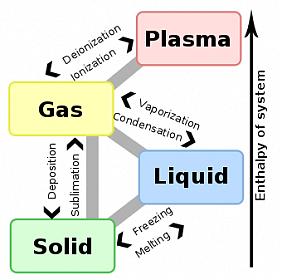
                              A phase transition is the transformation of a thermodynamic system from one phase or state of matter to another.

                              A phase of a thermodynamic system and the states of matter have uniform physical properties.

                              During a phase transition of a given medium certain properties of the medium change, often discontinuously, as a result of some external condition, such as temperature, pressure, and others. For example, a liquid may become gas upon heating to the boiling point, resulting in an abrupt change in volume. The measurement of the external conditions at which the transformation occurs is termed the phase transition point.

                              Phase transitions are common occurrences observed in nature and many engineering techniques exploit certain types of phase transition.

                              The term is most commonly used to describe transitions between solid, liquid and gaseous states of matter, in rare cases including plasma.

                              Critical points

                              In any system containing liquid and gaseous phases, there exists a special combination of pressure and temperature, known as the critical point, at which the transition between liquid and gas becomes a second-order transition.

                              Near the critical point, the fluid is sufficiently hot and compressed that the distinction between the liquid and gaseous phases is almost non-existent. This is associated with the phenomenon of critical opalescence, a milky appearance of the liquid due to density fluctuations at all possible wavelengths (including those of visible light).


                              Critical exponents and universality classesReal phase transitions exhibit power-law behavior.

                              Several other critical exponents - β, γ, δ, ν, and η - are defined, examining the power law behavior of a measurable physical quantity near the phase transition. Exponents are related by scaling relations such as β = γ / (δ − 1), ν = γ / (2 − η). It can be shown that there are only two independent exponents, e.g. ν and η.

                              It is a remarkable fact that phase transitions arising in different systems often possess the same set of critical exponents. This phenomenon is known as universality. For example, the critical exponents at the liquid-gas critical point have been found to be independent of the chemical composition of the fluid. More amazingly, but understandable from above, they are an exact match for the critical exponents of the ferromagnetic phase transition in uniaxial magnets.

                              Such systems are said to be in the same universality class. Universality is a prediction of the renormalization group theory of phase transitions, which states that the thermodynamic properties of a system near a phase transition depend only on a small number of features, such as dimensionality and symmetry, and are insensitive to the underlying microscopic properties of the system. Again, the divergency of the correlation length is the essential point.

                              Critical slowing down and other phenomena

                              There are also other critical phenoma; e.g., besides static functions there is also critical dynamics. As a consequence, at a phase transition one may observe critical slowing down or speeding up. The large static universality classes of a continuous phase transition split into smaller dynamic universality classes. In addition to the critical exponents, there are also universal relations for certain static or dynamic functions of the magnetic fields and temperature differences from the critical value.

                              Percolation theory

                              Another phenomenon which shows phase transitions and critical exponents is percolation. The simplest example is perhaps percolation in a two dimensional square lattice. Sites are randomly occupied with probability p. For small values of p the occupied sites form only small clusters. At a certain threshold pc a giant cluster is formed and we have a second order phase transition. The behaviour of P∞ near pc is, P∞~(p-pc)β, where β is a critical exponent.

                              RM
                              Attached Files
                              Last edited by evolvingape; 02-22-2012, 03:41 PM.

                              Comment

                              Working...
                              X