
This forum is preserved as a permanent archive. The community continues at eMedia Press.

Announcement

Collapse
No announcement yet.

Garry Stanley Pulse Motor

Collapse
X
 
  • Filter
  • Time
  • Show
Clear All
new posts

  • Hello guys

    I have a question sorry if its a little off topic. I have one of Rick's 3-pole kits and have played around with different circuits and coil configurations. One thing that I discovered a while back was when I run a typical Bedini 1 transistor set up but instead of using a bifilar coil I use 2 seperate coils, 1 for the trigger and 1 for the power coil I get next to nothing as a back spike. With 3 single wire coils, one trigger and 2 power coils (connected in series) I only get a back spike of 1.2 volts on my meter, and of course no secondary charging. My input is 12 volts. With a bifiliar coil my input is about 150ma with the separate trigger and 2 power coils in parallel the input drops to 8-10ma.

    How come I don't have a back spike when I remove the trigger coil from the power coil? Is it just because the amp draw is so low?

    Thanks for any help, mark

    Comment


    • Originally posted by Mark View Post
      Hello guys

      I have a question sorry if its a little off topic. I have one of Rick's 3-pole kits and have played around with different circuits and coil configurations. One thing that I discovered a while back was when I run a typical Bedini 1 transistor set up but instead of using a bifilar coil I use 2 seperate coils, 1 for the trigger and 1 for the power coil I get next to nothing as a back spike. With 3 single wire coils, one trigger and 2 power coils (connected in series) I only get a back spike of 1.2 volts on my meter, and of course no secondary charging. My input is 12 volts. With a bifiliar coil my input is about 150ma with the separate trigger and 2 power coils in parallel the input drops to 8-10ma.

      How come I don't have a back spike when I remove the trigger coil from the power coil? Is it just because the amp draw is so low?

      Thanks for any help, mark
      Just a guess, but I'll bet it's slow switching speed. You're not going to get a nice sharp drive pulse from a separate coil. When a magnet passes a coil like yours, it usually induces a triangle waveform.
      When the switching coil is incorporated into the drive coil, it produces a nice sharp cutoff in the drive current due to mutual interaction between the drive pulse and the switch pulse. Fast switching is what creates a big spike.
      Try driving your transistors with a reed switch to see the difference.

      Ted

      Comment


      • Hi folks, Hi Ted, thanks for your thoughts. Sure, I'd like for you to explain this impedance matching concept, thanks. Hi woopy, what are you planning to build next, curious, thanks.
        peace love light
        Tyson

        Comment


        • Hi all

          Fantastic thread here

          Thank's Tyson for the link at Newmann theory. I have dared to make a pix of the graph showing the Ampere /turns staying stable as the wattage goes down.

          And of course i could not prevent me to make an exercise on your datas as per post 211.
          I hope i made no mistake, very impressive.

          I think that is why the Garry's motor seems so good , because he uses a lot of coils (surely paralleled ) but mainly in serie.

          My next project will evidently be something with a lot of coils in serie associated with a big voltage.

          @Ted of course i am interested of your circuit. We are going in a good direction here .

          good luck at all

          Laurent
          Last edited by woopy; 08-29-2010, 06:17 PM.

          Comment


          • Last edited by Turion; 01-13-2011, 11:35 PM.

            Comment


            • Very nice!!

              Very nice and well thought out rotor build. Great job. Now I guess I don't have any excuses for not making one, except getting the time of course. I really do want to try this when I get done with several other projects I am working on.
              Thanks for sharing your ideas, Carroll
              Just because someone disagrees with you does NOT make them your enemy. We can disagree without attacking someone.

              Comment


              • For the Gary Stanley motor you might want to just cut the two 12/ inch width smaller pieces of cuttingboard material as large in diameter as you can get them without screwing up the coils, glue them or screw them together, and eliminate the PVC. That would give you 1" between rotors which is enough for two coils back to back plus two 1/4 inch air gaps. If you want your air gaps smaller, substitute plexiglass for one of the pieces. It is usually 1/4 inch thick, and could lower the width of your air gap.

                Comment


                • Originally posted by garrys View Post
                  I have a bit of trouble understanding this since 2 coils either add together to make more bemf and thus are perfect in this configuration for a generator or they cancel each other out in potential or voltage if you like and therefore have no current flow ...without current flow there is no flux and so if there is no flux then there is no bemf and this would mean peter isnt interpreting his data correctly though i can see that this might cause the built flux field to be confused momentarily this would stil be too fast for anything to register it simply because the flux is moving faster than the speed of light.

                  Mine is about connecting 2 coils together in a sympathec maner to make the induction counter each other it is not restricted to the coil layout or parellal or series wiring as it works for both ways of wiring and still works when the coils are seperated rather than together, apart from the forward emf part which requires proximity of magnets.

                  Garry
                  Hi Garry,

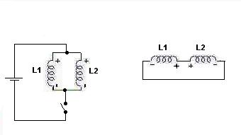
                  I made a little drawing with two paralleled coils first, both are wound in the same sense and suppose you pulse them as shown. Whenever you switch the current off, the two coils are left on their own, connected still in parallel but I drew them in a "series" arrangement to indicate their polarities oppose each other, this is how I am convinced they behave.
                  This means that at switchoff the induced BEMF from the collapsing fields in both also oppose each other but as there are always some small physical / constructional differences between coils the bucking fields cannot cancel immediately because their amplitudes are not perfectly equal, they need some time to cancel. This is utilized in Peter Lindemann's (heating) setup referred to.

                  In case of your two paralleled coils, the way as you describe how to connect them, I can only say that: when you turn the second coil 180 degree back with respect to the first one, (say, after 'cutting' a coil into two to get a first and a second coil), the winding sense does not change, it remains the same clockwise or counterclockwise like the first coil was, so when you switch current into this second coil the flux depends only on how you choose the input voltage polarity.

                  For me this means that your two coils also have bucking BEMF fields and as such they also cancel, this is why the rotor magnet pairs can move freely away after the current is switched off at TDC. There is Lenz during the attract time, from the current switch-on till current switch-off, and there is no Lenz of course after TDC as the magnet leave the coils till the next switch-on.

                  (Please recall when you loaded your shaft with your firm grip or with the bicycle wheel, the current consumption went up from a lower value to a higher one, this was due to normal Lenz law at the attract-in time.
                  Of course, when all the coils are in series like in Ian's setup, the same Lenz works during the attract-in time too.)

                  I understand you have a different view on the induction when speaking of the second coil turned back, and I also understand your firm determination on this and your great many practice finally lead to making a free energy device, and I would like to understand it very much, this is why I asked in the personal message, what has happened to it since October, 2003? Would you tell? Please do not avoid answering.

                  In my earlier drawing here:

                  I had thought the second coil had to have an opposite winding sense with respect to the first one: now after your recent description to woopy:

                  I think I have to correct it to have the same winding sense after turning it back. Can you agree with it?

                  Regards, Gyula
                  Attached Files
                  Last edited by gyula; 08-17-2010, 10:12 PM.

                  Comment


                  • Hi folks, Hi woopy thanks for the posts on post 211, look forward to your new motor setup. Hi turion, thanks for all the info on your motor, looks like a good design, i've seen that exact cutting board material at a big lots store by me. Yes, with that material and such large diameter rotors you probably need extra wide center support. Woopy's design is good, however it may cause too long of a pulse width, i think the shortest pulse width is the most efficient. Ted's design is one I've built myself and know first hand how the neos power can bend the rotors and so as we've discussed, a strong steel rotor disc would be needed and at the same time would serve as a flux bridge backing and another nice thing is you could fit in more coils on the center stator plate. Hi gyula, thanks for your thoughts on the parallel aspect. Here is 2 designs for air-core pulse motors, the one on left is woopy's design and the one on right is Ted's. I think woopy's design would be easier to build, though it can't fit as many coils. Though Ted's has to be built larger and there may be an issue with the magnets being at different radius. Though one nice thing is, magnets could be mounted on opposite sides of steel rotor discs if one wanted to put multiple rotors on same shaft. What do you folks think, maybe these designs are overkill.
                    http://a.imageshack.us/img820/8370/2...motordesig.png
                    peace love light
                    Tyson

                    Comment


                    • or this design with 16 coils and 16 magnets with alternating magnet polarities. Though it would still be uni directional pulsing, unless one wanted to switch coil polarities, though that would be a rather complicated drive circuit.
                      http://a.imageshack.us/img801/2628/1...ircoredesi.png
                      peace love light
                      Tyson

                      Comment


                      • Hi again folks, just had a thought about this 16 coil/16 magnet design. If one added another stator on same shaft with another steel disc with 16 magnets then all that would be needed for drive circuit would be another transistor and sensor to fire the other separate stator when the first stator is de-energized and this would give just about constant torque throughout the cycle. And more rotors and stators could be added to shaft for even more shaft torque.
                        peace love light
                        Tyson

                        Comment


                        • Originally posted by SkyWatcher View Post
                          Hi again folks, just had a thought about this 16 coil/16 magnet design. If one added another stator on same shaft with another steel disc with 16 magnets then all that would be needed for drive circuit would be another transistor and sensor to fire the other separate stator when the first stator is de-energized and this would give just about constant torque throughout the cycle. And more rotors and stators could be added to shaft for even more shaft torque.
                          peace love light
                          Tyson
                          Hi Tyson,

                          I like these setups you describe because they have several magnets and coils and one thing is sure this tendency helps getting higher torque.

                          Somehow we ought to understand what Garry is trying to tell us... and my problem is why he states that turning back a coil with respect to a first identical coil (see above as he exactly described), the induction in it changes? because the winding sense does not change when you turn back a coil 180 degree.
                          And some tests can only tell whether such paralleled coils like 12 pair of them with the corresponding 12 magnet pairs outperform an equivalent series coil setup. Unfortunately, those flat coils Garry used are hard to obtain nowadays.

                          rgds, Gyula

                          Comment


                          • Originally posted by gyula View Post
                            Hi Tyson,

                            I like these setups you describe because they have several magnets and coils and one thing is sure this tendency helps getting higher torque.

                            Somehow we ought to understand what Garry is trying to tell us... and my problem is why he states that turning back a coil with respect to a first identical coil (see above as he exactly described), the induction in it changes? because the winding sense does not change when you turn back a coil 180 degree.
                            And some tests can only tell whether such paralleled coils like 12 pair of them with the corresponding 12 magnet pairs outperform an equivalent series coil setup. Unfortunately, those flat coils Garry used are hard to obtain nowadays.

                            rgds, Gyula
                            standard 3 1/2 floppy drive with motor similar to the picture have smaller coils similar to 5 1/4
                            Last edited by wings; 11-01-2012, 08:51 PM.

                            Comment


                            • Originally posted by woopy View Post
                              @ Ted

                              Thank's a lot for the advice and math, will help for my next building.

                              @ Matt
                              Yes could be good , have you a shematic ?

                              @ Garry
                              Thank's i think i have grasped something and i have made a drawing of what i think you are meaning in your previous post. Is it correct ?.

                              @ all

                              And i made a small test to crudely compare my Garry's understanding with Gyula's drawing from some posts ago, and one single coil.
                              Please find enclosed the report.

                              I have also enclosed the set up of the test where you can see the black plastic bloc supporting on one side the double coil and than i simply have to flip the bloc to test the single coil.

                              Finally i enclose a pix where you can see the scope trace on a Garry's parallel config. There is a clear generative wave. So this config seems not to stop the generator in the motor.

                              But nothing very new as the double coils (named by me Garry's and Gyula's )
                              are about the same resistance and inductance when wired in serie as the single coil, and they work about identical.
                              But once wired in parallel they simply draw about twice the ma for the same work.
                              So as per my understanding there is no advantage in this concept.

                              Where do i miss something.?

                              Perhaps i have to do a bigger test jig to have better results but i am in serious doubt and i think that the serie config is THE way to go.

                              What do you think ?

                              good luck at all

                              Laurent
                              Hi Laurent ...your 3rd pic in your drawing is wrong you have not turned around the second coil but have simply rewired it ..... leave the wires and turn the coil round this will make the poles correct and the flow will now be opposed to the first one.

                              Garry

                              Comment


                              • Hi wings, thanks for that information. Hi gyula, thanks for your thoughts. I think your thought that his motor performed better with the 12 coil pairs because of the added copper of the coils is the answer. Though I never did see his comments about it performing worse when he reduced the magnets and active coils to 6 per side, but if that is true, then less copper means less shaft work for a given input. Also, the compression of permanent magnet flux using dual rotors which prevents deflection is another thing that makes this type of motor so good as far as air-core coil motors go, as garry has pointed out. Yes those designs I posted, I will be building the woopy type design, though without flux bridge backers and I will be using 12 coils and 6 magnets per rotor for now since that's all the magnets I have right now. When I get more funds, I can expand the rotors to 12 magnet stacks per rotor, or for now I could just reduce size of magnet stacks to 3/8" depth instead of 3/4" and this way i could have the 12 magnets per rotor, though the flux field across coils will be 1/2 as much. Then later I can expand the motor. Here is the design layout.
                                http://a.imageshack.us/img818/7303/p...ign12magne.png
                                peace love light
                                Tyson

                                Comment

                                Working...
                                X