

 Tweet
Tweet
Attached Files
-
-
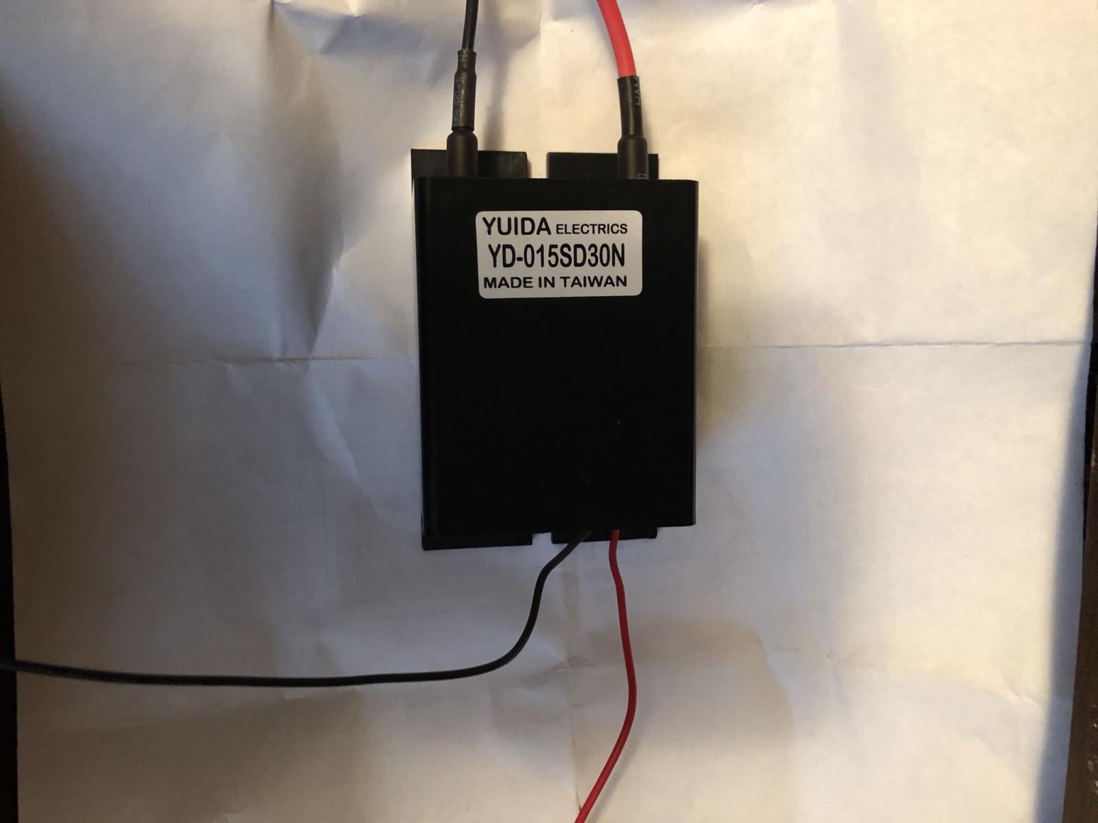
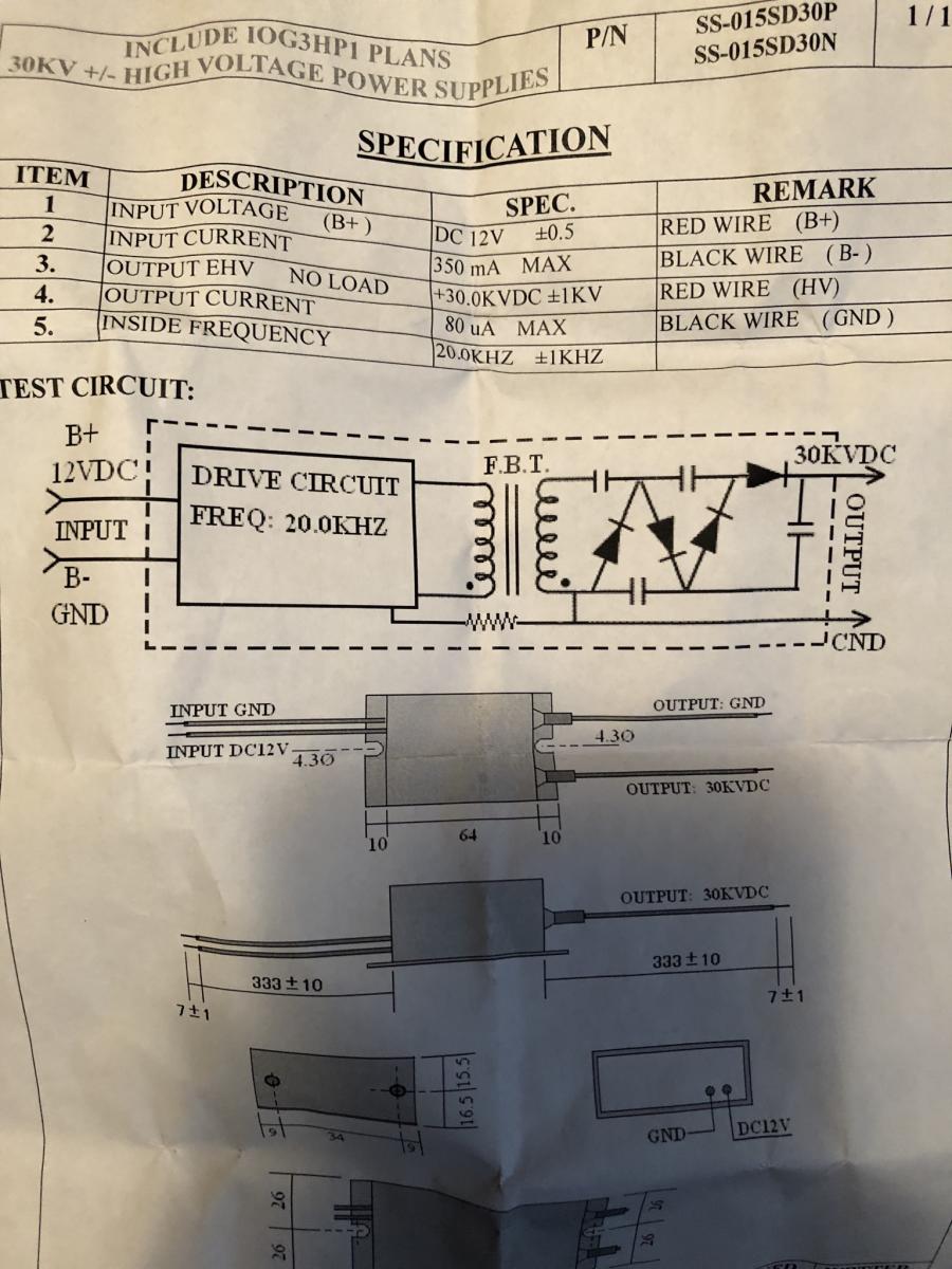
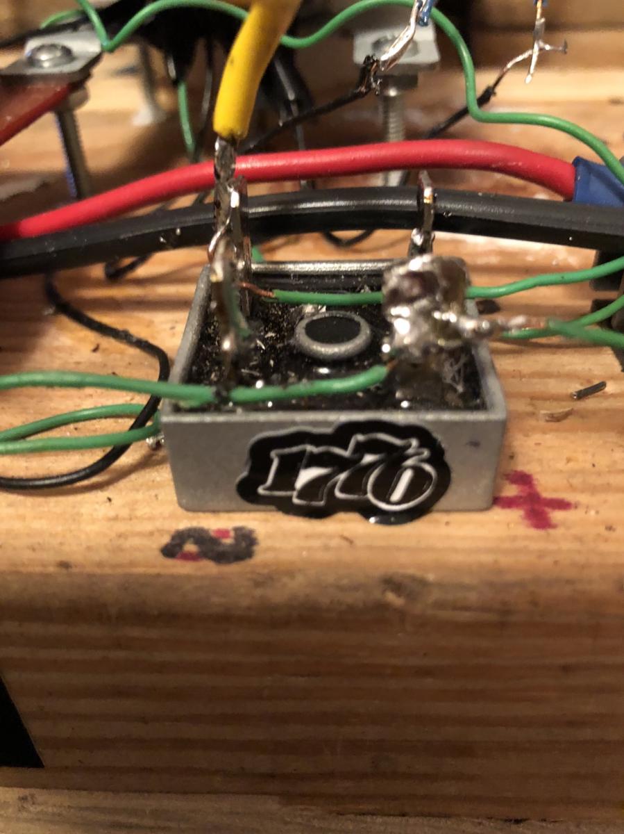
I have this dc to dc stepup transformer.Attached FilesComment
-
-
Originally posted by Pot head View Post
Are you talking to me? I am not questioning the possibilities here.
Can you show a circuit or a direction to go in? Is this a Don Smith?
What does the spark gap do to help this? If any. No spark gap?
HV can be fun.Comment
-
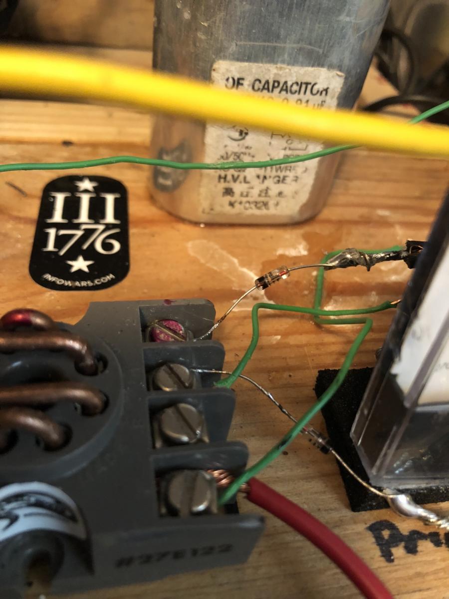
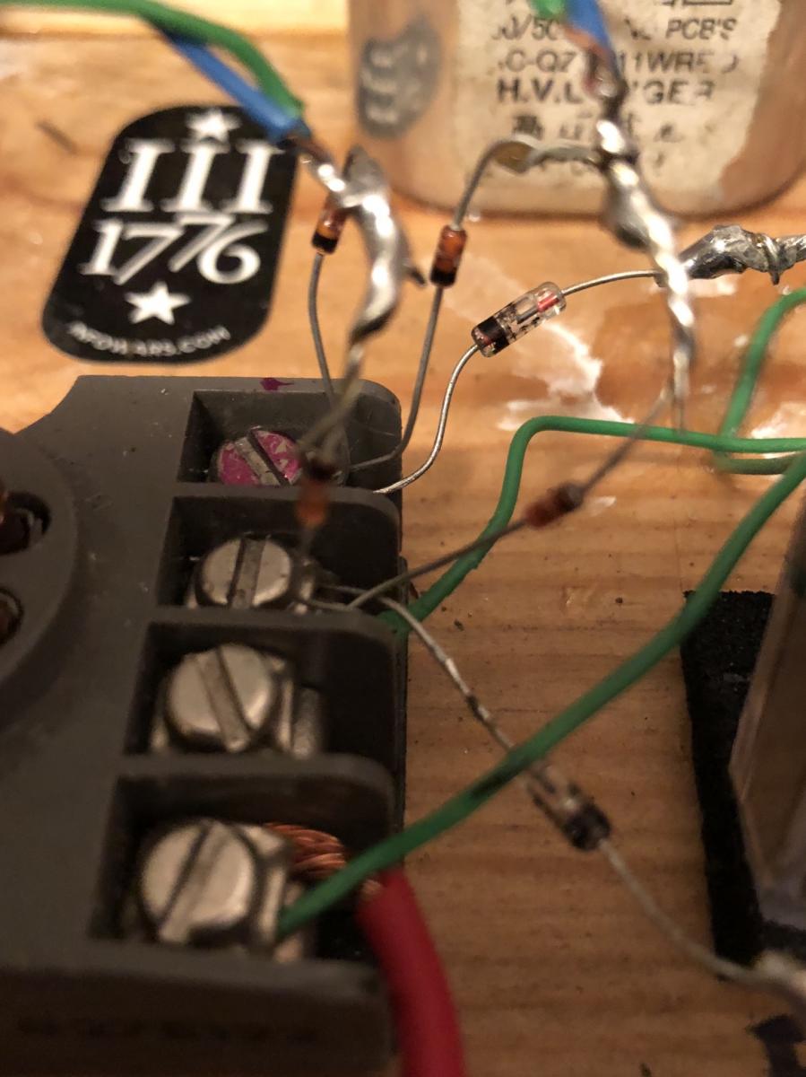
I took the two stator outputs and disconnected them from the bridge rectifier and attached two smaller Zener to the outputs making four diodes total so the drop voltage will be smaller and a larger dc voltage.Attached FilesComment
-
-
Ionic wind, Tesla coil transmission, wireless dc to dc transmission over long distances.
Some possibilities for an HV to be used to teach others on a smaller scale what Eric Dollard is doing in larger detail and scale.
It may help some people.Comment
-
Who is Don Smith?
I will try to reason out a schematic among all the wire Jungle vines.Comment
-
-
hi BroMikey
please check your pm box, I have a questionComment
-
I have a question, why are you using this thread for your text message?Comment
-
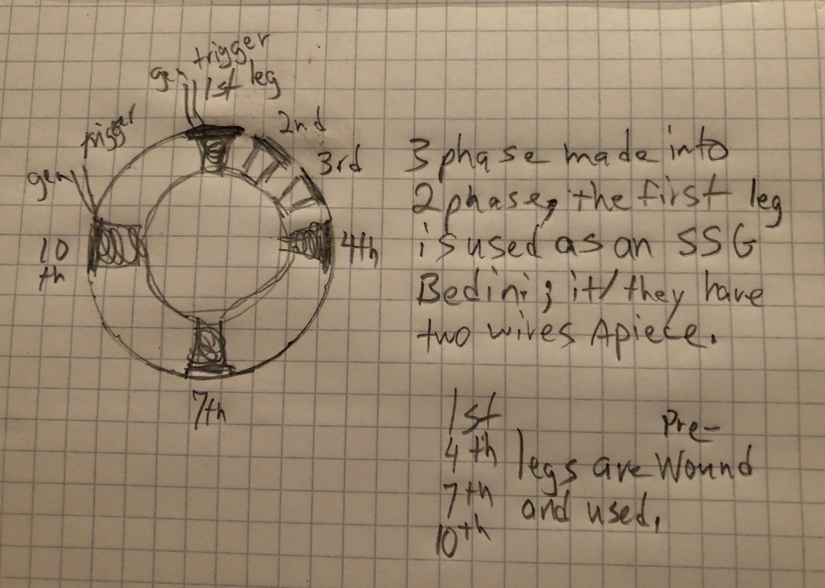
Here is a drawing of the stator arrangement.
The first, fourth, seventh and tenth legs are used and the other legs are dumped into a microwave capacitor then rectified using small zener diodes and then fed into the primary side.Attached FilesComment
-
-
The circuit is using nsnsns magnets instead of nnnnnn.
I plan on making a 24 magnet rotor that is both inside and outside of the rotor shell by drilling holes and using the same 24 for both low drag coil and the Bedini circuit opposite each other in application.
Since the inner ring magnet is an 8 configuration, I reasoned that 8x3 24, it should work.
Guys and dolls? Your thoughts?Comment
-
-
One of them. The circuit feeds the one transistor Bedini layout like the TeslaGenX circuit board. The input and output have capacitor reinforcement to keep the circuit balance, it keeps the transistor from blowing just like the neon, but it allows extra time in case the charge battery accidentally gets unhooked.
The primary has five parallel caps to store the input voltages from various places.
I will draw more when I physically feel better. My age is about yours BroMikey,
Just be patient, thanks.Comment
-
Okay, yes Sir, got to show respect to the eldersOriginally posted by Pot head View Post and that other guy?
Using your thread, I don't know who he is (sending me a private message)
Who the hell is Dogg2shoes?
Either way I got to see your git up when you run it.Last edited by BroMikey; 04-02-2019, 09:22 PM.Comment
-
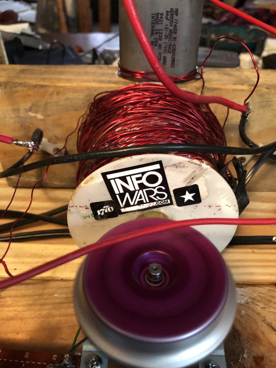
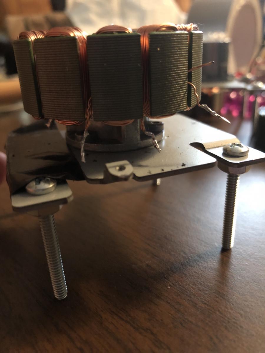
A photo of one of the coils, each phase has two wires of equal size.
Then like in the photo, the pair are used in ssg format.
The other two phases are left alone and ac is rectified across some tiny zener diodes.
Before the ac to dc transformation the ac is passed through a microwave capacitor for stronger emf.
Now the question of 24 magnets, 12 n and 12 s; the opposite side of the configuration on the outside would go across the low drag generator coil.
I will drill holes for this.Attached FilesComment
-

Comment