This forum is preserved as a permanent archive. The community continues at eMedia Press.

Announcement

Collapse
No announcement yet.

Bucking Coil Inverter

Collapse
X
 
  • Filter
  • Time
  • Show
Clear All
new posts

  • hi sky. sounds like adding a relay buzzer circuit to the input might be suitable. might need more volts. maybe a 5v relay would go on 3.5-3.7v. can add a diagram if helpful.
    cheers
    Last edited by voltan; 02-21-2015, 11:07 PM.

    Comment


    • Hi folks!
      Sky, great test my freind seems we could acheive a good battery charger this way...
      Voltan i think your idea to use a relay in self oscillation is a good thing to try. I may have the part to try it... I will let you know from the result.
      Ciao!

      Comment


      • hi all. here's a snippet of info quoted from the don smith thread.

        But with a split secondary consisting of a CW and a CCW winding there is also a 90deg shift between the CW and the CCW turns.That means that when CW winding delivers voltage the CCW winding delivers current and viceversa.
        * i'm guessing that's at resonance. it might be more applicable to 2 layers wound the length of a rod than half length bucking coils, but i think it's important to understand the phasing of partnered coil arrangements. sounds like a job for a dual trace scope. food for thought.
        cheers
        Last edited by voltan; 02-25-2015, 11:14 PM.

        Comment


        • my new test...

          Hi folks!
          Here is my new interesting test....

          Hope you envoy!
          Ciao!

          Comment


          • Originally posted by Wistiti View Post
            Hi folks!
            Here is my new interesting test....

            Hope you envoy!
            Ciao!
            Well, by my calculations that is a COP > 1.0 BUT...

            You would still have to put the output on a scope and determine if the waveform is a pure sine wave. If it is, nice work! If it isn't, hmmm... Curious how the waveform is being modified.

            Comment


            • I just found this:

              [VIDEO]https://www.youtube.com/watch?v=qq_FAwTYlMg[/VIDEO]

              Very interesting.

              I theorize that for greatly increased output, one could continue the Bucking Coil copper winding with another second Outside Set such that the green output coil is sandwiched in-between the first and second set.

              Just keep paying attention to the right hand rule, remembering that the magnetic flow is in the other direction on the outside of each coil (not visualized in the video).
              Last edited by MagnaMoRo; 05-26-2015, 11:46 PM.

              Comment


              • Agree.This is the (one of many) solution.

                Comment


                • Bucking Coil PDF

                  [VIDEO]https://www.youtube.com/watch?v=iUy_9jDKDvo[/VIDEO]
                  Code:
                  https://www.youtube.com/watch?v=iUy_9jDKDvo
                  [VIDEO]https://www.youtube.com/watch?v=hvUiQ3IMHMU[/VIDEO]
                  Code:
                  https://www.youtube.com/watch?v=hvUiQ3IMHMU
                  www.hyiq.org/Downloads/Guidelines%20to%20Bucking%20Coils.pdf

                  Bucking Coils PDF
                  Last edited by vidbid; 05-28-2015, 04:09 AM.
                  Regards,

                  VIDBID

                  Comment


                  • This is the most important piece of information in the whole pdf.

                    "What does Work"


                    So, my last post was wrong. The green wire in the video is the "excitation wire" or input wire, needing an AC signal.

                    Still, I could see an L4 coil added in, in phase with L1 and wrapped around L3 with L3 wrapped around L1 for increased efficiency.

                    Comment


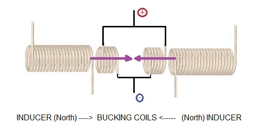
                    • This is a configuration that -I think- should cancel completely the Lenz effect resulting from the group of two bucking induced coils:

                      Two inducers and two output bucking coils. Inducers have like poles facing each other (North - North , or South - South ) , therefore the system is simetric and each induced coil is trasversed for each inducer field. The induced current add up to contribute to the final voltage output, while at the same time both induced field cancell each other.


                      INDUCER (North) -----> TWO BUCKING COILS <----- (North) INDUCER


                      Where both inducers are creating a North pole toward each bucking coil (same inducer poles facing each other North-North). This way each bucking coil is transversed by a different inducer field .Connecting properly the induced coils both induced voltages add up, while both induced magnetic fields cancel out.

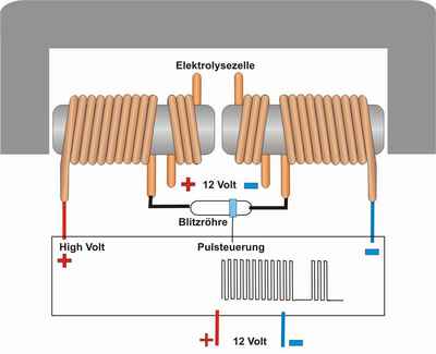
                      PS. This configuration was supposed to be used by Daniel Dingel in his water powered car:

                      Attached Files
                      Last edited by hanon1492; 07-12-2015, 04:57 PM.
                      https://figueragenerator.wordpress.com/

                      Comment


                      • Sorry. Just chiming in for a short hint.
                        A solar cell is a good measure for dealing with light intensity / power. It is simple, cheap, fast and can be done quite scientifically in order to perform solid proof of output power.


                        1. Comparing the luminosity of a light source:


                        2. Calibrating a light source:

                        That amount of info shall suffice for now but I am prepared to elaborate on request.
                        Last edited by JohnStone; 07-14-2015, 12:57 PM.
                        Experts spend hours a day in order to question their doing while others stopped thinking feeling they were professionals.

                        Comment


                        • JohnStone

                          Can I ask btw if you know good way to force n-channel mosfet which has microseconds switching time in datasheet to switch at nanoseconds ?

                          Comment


                          • @Boguslaw: That is a science in itself. FETs are incredibly fast in switching by nature (ps). But the capacitance of the gate is the restriction. The more amperage the more delay.
                            Unfortunately the voltage at drain penetrates to gate via capacitive effects and tends to charge the gate cap while opposing the switching action.
                            We can get very good dedicated FET drivers that can drive in excess of 5A for short time. Here the restriction is the PCB design or wiring. If done not properly all efforts do not work as expected.
                            You might remember me monster driver design I gave to UFO thread. There I summed up all necessary for a fast driver. I did all I could for DIY through hole PCB. SMD will be far superior if optimized.
                            In laser technology they get the gate capacitance discharged (switch off) by applying a very short negative HV pulse tuned to the very capacitance of the FET. You shall understand that data sheets state standard conditions based on published test circuits. They cover usual use. Nevertheless semiconductors own many unpublished properties that can be used if "skilled in the art".
                            Meanwhile CREE has very fast silicon carbide FETs in portfolio that are inherently HV and ns switching time - and affordable. But please keep in mind that the wiring is here the essential ingredient - FAT, SHORT, STRAIGHT, SMD components ..... Not to forget fast ceramic capacitors for drivers.
                            If you have done all right, you will detect that some components are too fast and ringing issues arrive. Then you must tune those components to get slower. But if you have a slow oscilloscope you never will see those issues.
                            In fact short switching time needs HF design rules regarded. A spark gap does all these miracles for free.
                            Sorry - no easy answer :-)
                            Last edited by JohnStone; 07-22-2015, 12:48 PM.
                            Experts spend hours a day in order to question their doing while others stopped thinking feeling they were professionals.

                            Comment


                            • Because the world energy consumption is presently fossil fuel and electromagnetic generated in Terra Watts, Thermal BTU and horse power are the units presently used.

                              Light is not much of a problem any more and the units do not work well at all.
                              The fanciful use of light and it's array of spectra has little to do with the real problem.
                              So light as a comparison is another distraction. Torque is being used alright.

                              Comment


                              • Nikola Tesla's Bucking Induction Coil

                                In one of Tesla's lectures, he describes the construction of a induction coil which is a bucking coil design. He said that the "electromagnetic fields cancel" in the space between the coils. He also said that the "electrostatic" effects at the open end were "sufficient" to replicate most of the interesting high frequency phenomenon he describes in his lectures. I am building a replication of it and running it with an LMD Analog computer, I will post my results in this thread.
                                Bucking coils certainly exhibit strange properties when they are put under load, though.
                                At resonance, properly constructed bucking coils are OU.
                                Bedini's Kromrey Converter uses them as well.

                                Comment

                                Working...
                                X